Laminated polyester resin container and method of molding such a container

Inactive Publication Date: 2008-12-02
YOSHINO KOGYOSHO CO LTD
View PDF15 Cites 8 Cited by
  • Summary
  • Abstract
  • Description
  • Claims
  • Application Information

AI Technical Summary

Benefits of technology

[0030]Laminated containers comprise a gas barrier resin layer or layers having low mechanical properties, and the gas barrier layer or layers have to be as thin as possible to make sure that these intermediate layers are transparent in the multilayer preforms. However, when these preforms are subjected to double or two-step blow molding, the PET

Problems solved by technology

Although PET resin containers have so many quite excellent properties, even PET resin containers fall short of the gas barrier property against oxygen in the air, especially in cases where the foods, with which bottles are filled, require a high air-blocking property.
Because of such low gas barrier properties, the food may lose its taste or food spoilage may result.
Thus, an unsatisfactory point still remains.
However, the hollow containers thus obtained were not acceptable as commercial products because the crystallizing and/or clouding phenomenon occurs between the inner and outer layers when the preform is obtained by laminating different resins, one by one, by the conventional injection molding method.
As a result, the blow moldability of the preform gets worse and its adhesive property decreases at the interface between resin layers.
Although MXD-6 nylon and ethylene vinyl alcohol copolymer resins have high gas barrier properties, they have also unfavorable mechanical properties and low degrees o

Method used


Image

  • Laminated polyester resin container and method of molding such a container
  • Laminated polyester resin container and method of molding such a container
  • Laminated polyester resin container and method of molding such a container

Examples


Example

EXAMPLE 1

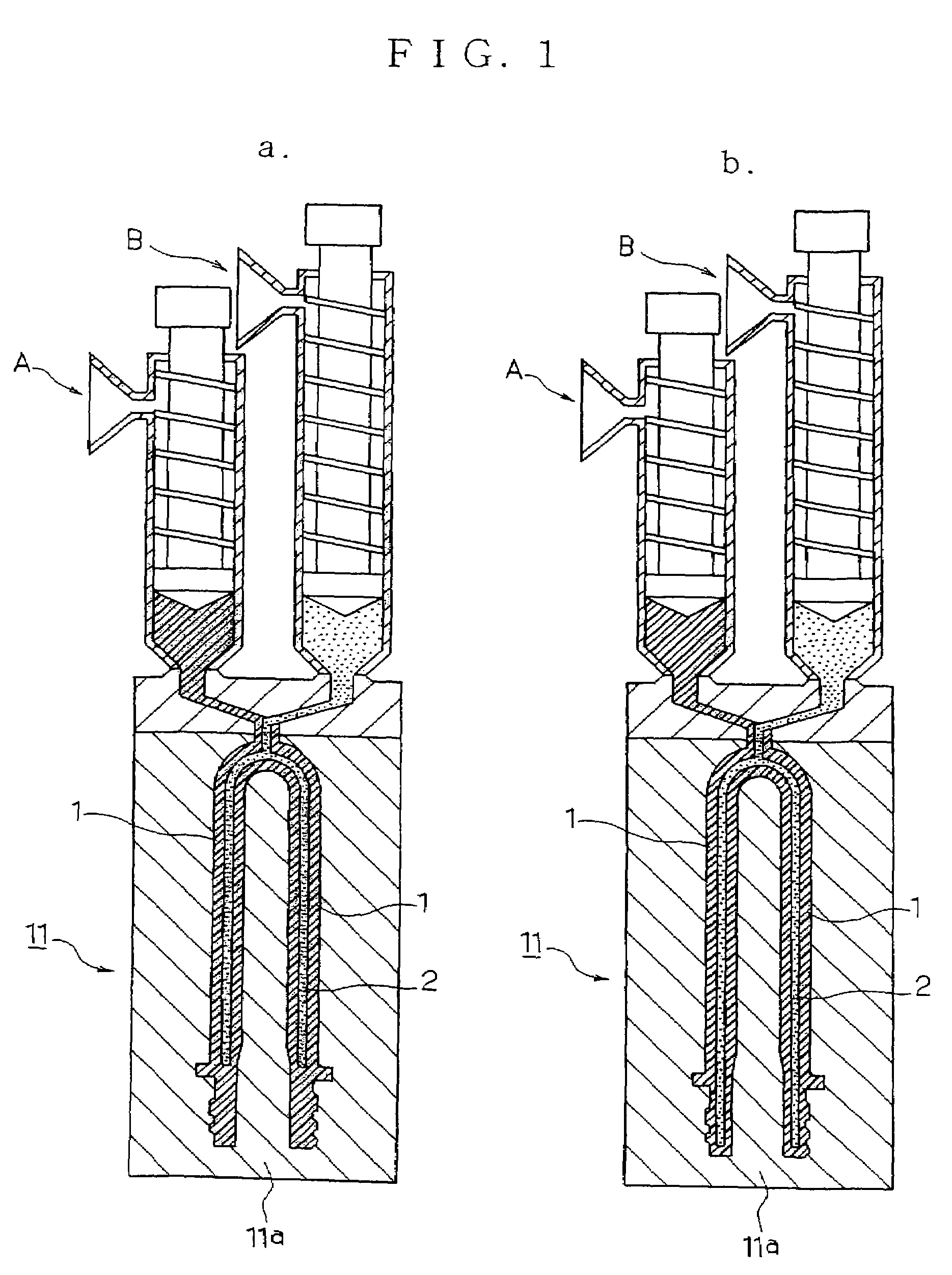
[0038]When the biaxially oriented blow molding method of this invention was used to mold a multilayer container, the first injection-molding machine A was fed with the PET resin to form the innermost layer and the outer layer, and the second injection-molding machine B was fed with the MXD-6 nylon resin to form the middle gas barrier layer, as shown in FIGS. 1a and 1b. After each resin was molten and kneaded, the molten PET resin was injected from the first injection-molding machine A into the injection mold 11. Then, with a slight time lag, the MXD-6 nylon resin was injected only in a given amount from the second injection-molding machine B. When the injection of MXD-6 nylon resin from the second machine B was stopped halfway, the preform P thus formed was composed of the inner and outer layers 1, 1 of PET resin, plus a middle layer 2 of MXD-6 nylon. The preform P of a 3-layer structure had a predetermined shape that corresponded to the shape of the finished molded product...

Example

EXAMPLE 2

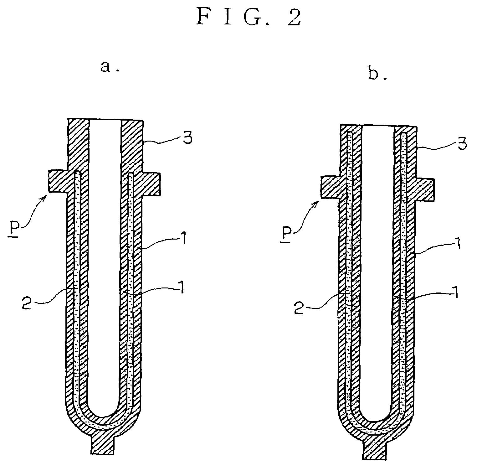
[0047]When such a 5-layer preform as used in the above inventions is utilized in this invention to mold a laminated container in a manner similar to Example 1, it is necessary to operate jointly both of the first injection molding machine A for injecting the PET resin such as used in Example 1 and the second injection molding machine B for injecting the gas barrier layers. The 5-layer preform is prepared by performing the injection molding in the manner described in the next paragraph.

[0048]First of all, the molten PET resin in the first injection-molding machine A was injected into the injection mold, and soon the injecting operation was tentatively stopped. Then, the MXD-6 nylon resin was immediately injected from the second injection-molding machine B, and soon the injecting operation was stopped. The PET resin was again injected from the first injection-molding machine A, and the mold was cooled while the pressure was maintained. A 5-layer preform P′ of a given shape wa...

Example

EXAMPLE 3

[0057]A preform P′ was molded in a similar manner as in Example 2, except that MXD-6 nylon resin layers 9a and 9b were given a somewhat lower thickness than in the 5-layer preform of Example 2 shown in FIG. 5.

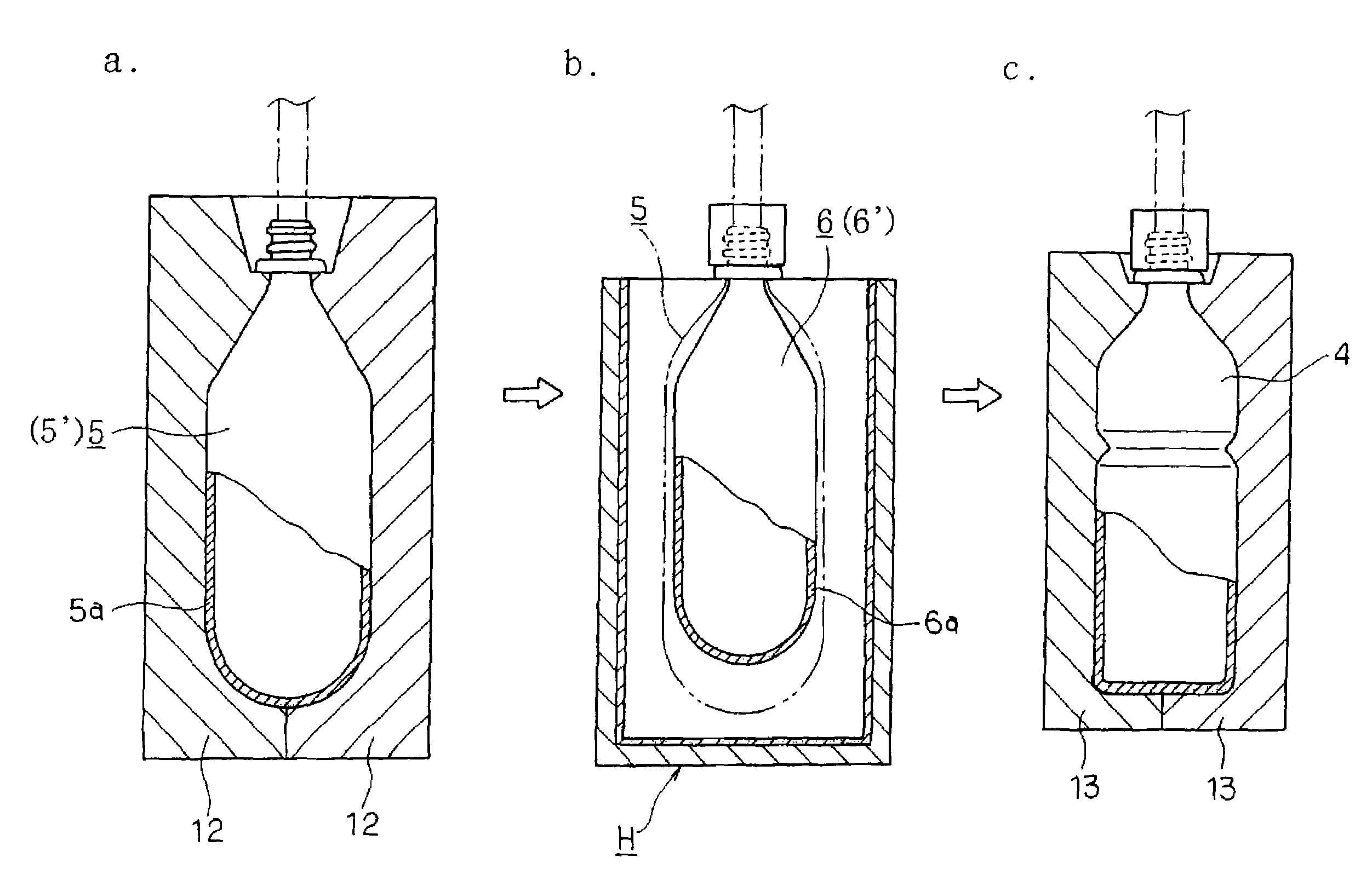
[0058]Following the same method as in Example 2, the preform mouth / neck portion 3′, which was to become the mouth of a container, such as a bottle, was treated for whitening to crystallize this portion without causing no thermal deformation. After the preform body portion to be biaxially blown was heated to a blow moldable temperature, which was close to the temperature of thermal crystallization, the preform was set in the primary blow mold, where the trunk portion had been heated to 160 deg C., and the bottom, to 23 deg C. The biaxially oriented blow molding was conducted at a pressure of 26 kg / cm2 for 2.63 sec to give the primary molded intermediate.

[0059]It was found that a favorable primary intermediate of a given shape could be obtained by the primary blow moldin...


PUM

PropertyMeasurementUnit
Temperatureaaaaaaaaaa

Abstract

A multiplayer perform having at least a medium or intermediate gas barrier layer is prepared in advance by the injection molding of this perform in a predetermined shape that corresponds to the shape of a finished molded product. The body portion of this perform is heated to a blow moldable temperature. The heated perform is set in a primary blow mold (12), and is blow molded in the biaxial orientation to give a primary molded intermediate (5). The primary intermediate (5) is then heated to deform it forcibly by thermal shrinkage and thereby to give the secondary molded intermediate (6). The shrunken secondary intermediate (6) is set in a secondary blow mold (13), and is subjected to the secondary blow molding in the biaxial orientation to obtain a finished molded product, which is fixed thermally to give heat history to the PET resin. As a result, the PET resin layers are given a high degree of crystallization, which serves to complement the function of the gas barrier layer or layers in such a way that the container has high and effective gas barrier properties.

Description

[0001]This is a divisional application of prior application Ser. No. 09 / 869,694, filed Jul. 3, 2001 now abandoned, which is a U.S. National Stage of PCT / JP00 / 08388, filed Nov. 29, 2000.BACKGROUND OF THE INVENTION[0002]1. Field of Invention[0003]This invention relates to a laminated polyester resin container and the method of molding such a container. More particularly, this invention relates to a laminated, biaxially oriented container of a thermoplastic polyester, including polyethylene terephthalate as the major component, which is laminated with a thin, clear film layer having high gas barrier properties; and to the method of molding such a container.[0004]2. Description of Related Art[0005]The polyethylene terephthalate resin (hereinafter referred to as PET resin) is a representative thermoplastic polyester resin known to have stable physical properties, antipollution property, an outstanding degree of transparency, and a high mechanical strength. Because of these favorable prop...

Claims


Application Information

Patent Timeline
IPC IPC(8): B29C49/22B29C49/00B29C49/06B29C49/18B29C49/64B65D1/02
CPCB29C49/18B29C49/221B29C49/649B65D1/0215B29B2911/1402Y10S264/906B29B2911/14053B29B2911/1406B29B2911/14066B29B2911/1408B29B2911/14093B29B2911/1412B29B2911/14126B29B2911/14146B29B2911/14153B29B2911/14326B29B2911/14333B29B2911/1444B29B2911/14466B29C49/0073B29C49/06B29K2067/00B29K2995/0041B29K2995/0067Y10T428/1341Y10T428/1352Y10T428/13B29B2911/14026B29C2949/3009B29C2949/3008B29C2949/3012B29C2949/3016B29C2949/302B29C2949/303B29C2949/3036B29C2949/3028B29C2949/24B29C2949/22B29C2949/3038B29C2949/0723B29C2949/0732B29C2949/073B29C2949/072B29C2949/0777B29C2949/0773B29C49/6472B29C49/642B29C2949/3032B29C49/071B29C49/42832B29C2949/0715B29C49/6605B29C2049/7862B29C2049/78645
Inventor OTA, AKIHOUESUGI, DAISUKESUZUKI, MASATO
Owner YOSHINO KOGYOSHO CO LTD
Why Eureka
Try Eureka