Method of decarbonating a combustion fume with extraction of the solvent contained in the purified fume

a technology of combustion fume and solvent, which is applied in the direction of combustible gas purification/modification, hydrogen sulfides, separation processes, etc., can solve the problems of solvent loss, method penalization, and all the higher losses

Inactive Publication Date: 2008-12-02
INST FR DU PETROLE
View PDF6 Cites 45 Cited by
  • Summary
  • Abstract
  • Description
  • Claims
  • Application Information

AI Technical Summary

Benefits of technology

[0026]Advantageously, the method according to the invention allows to recover the volatile compounds of the solvent carried along by the decarbonated fume. The solvent is recovered at a high level of purity, and this level can be compatible with recycling to the process.

Problems solved by technology

These methods are however penalized by the solvent losses due to the solvent saturation of the fumes treated and to the solvent being mechanically carried along in the fumes.
These losses are all the higher since the solvent constituents have a high vapour pressure.

Method used


Image

  • Method of decarbonating a combustion fume with extraction of the solvent contained in the purified fume
  • Method of decarbonating a combustion fume with extraction of the solvent contained in the purified fume
  • Method of decarbonating a combustion fume with extraction of the solvent contained in the purified fume

Examples


Embodiment Construction

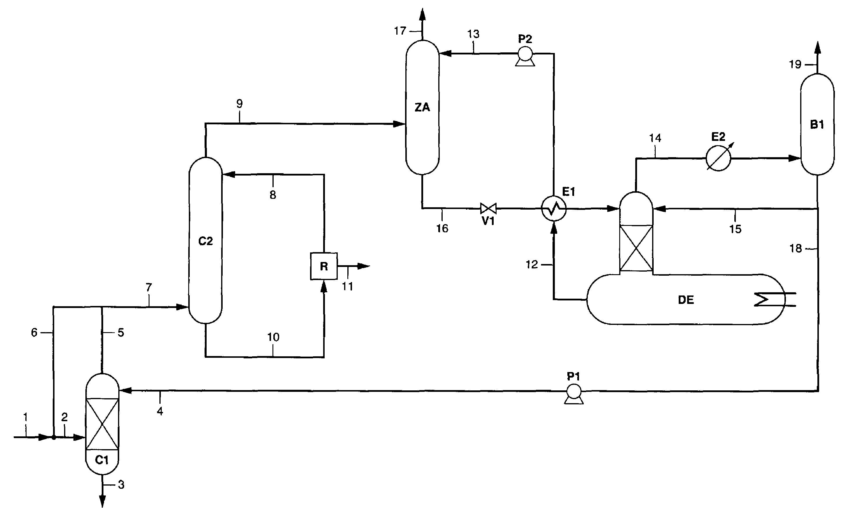
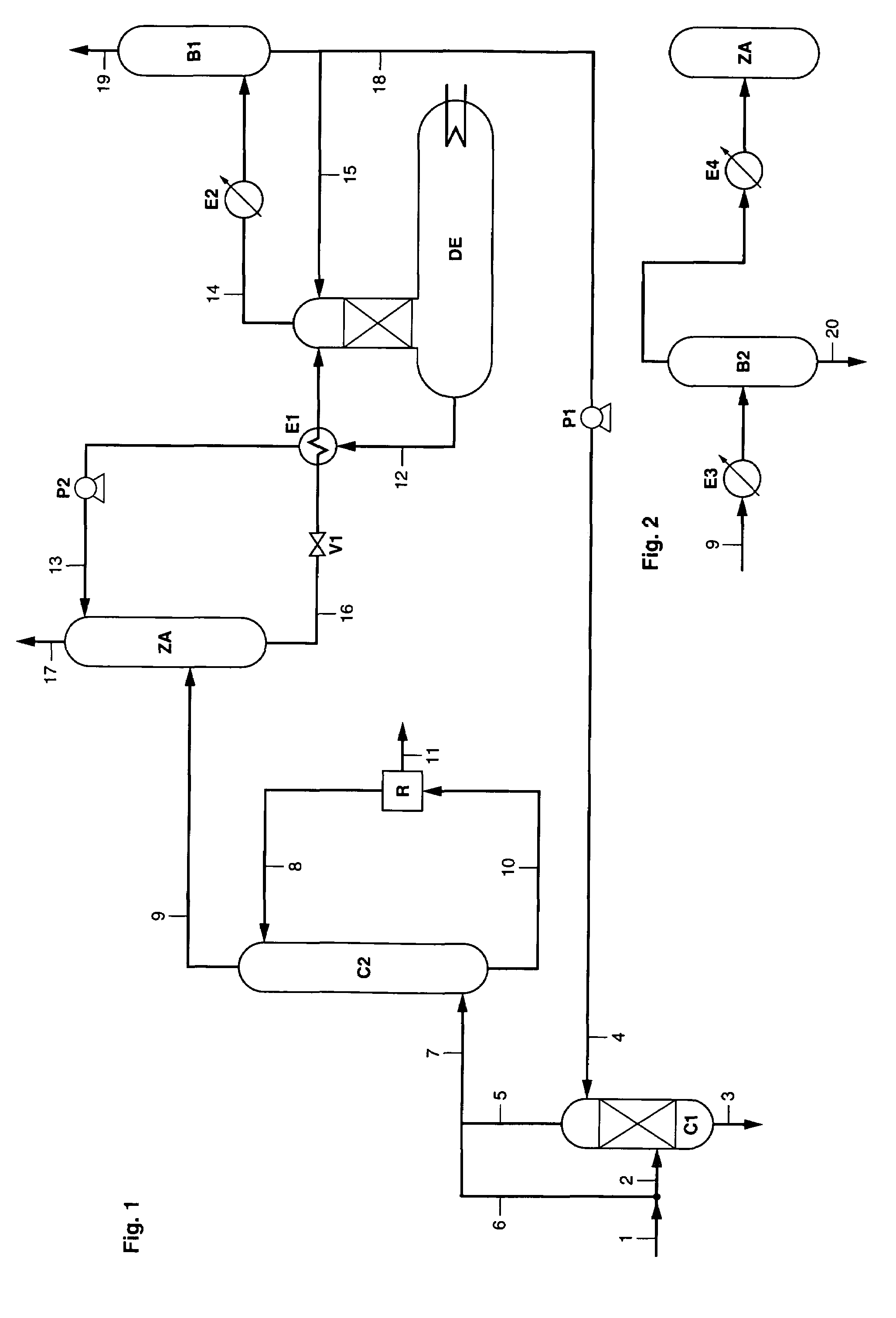
[0028]In FIG. 1, the fume to be treated flows in through line 1. For example, the fume resulting from the combustion of natural gas, of fuel oil or of coal contains 50% to 80% nitrogen, 5% to 20% CO2, 2% to 10% O2, and various impurities such as sulfur oxides (SOx), nitrogen oxides (NOx), dusts or other particles. The fume can be available at a pressure ranging between 1 and 100 bars, preferably ranging between 1 and 5 bars, and at a temperature ranging between 20° C. and 300° C., preferably between 40° C. and 180° C. Furthermore, the fume can be saturated with water. The temperature and the pressure of the gas mixture can be controlled in order to correspond to the ideal operating conditions of column C2. For example, the fume flowing in through line 1 is subjected to compression and / or cooling. A separator drum can be used to separate a possibly condensed fraction.

[0029]A fraction of the fume can be fed through line 2 into contacting zone C1, where it is contacted with a solvent-c...


PUM

PropertyMeasurementUnit
pressureaaaaaaaaaa
temperatureaaaaaaaaaa

Abstract

The combustion fume flowing in through line 1 is decarbonated by contacting with a solvent in column C2. The solvent laden with carbon dioxide is regenerated in zone R. The purified fume discharged through line 9 comprises part of the solvent. The method allows to extract the solvent contained in the purified fume. The purified fume is contacted in zone ZA with a non-aqueous ionic liquid of general formula Q+ A−; Q+ designates an ammonium, phosphonium and / or sulfonium cation, and A− an anion likely to form a liquid salt. The solvent-depleted purified fume is discharged through line 17. The solvent-laden ionic liquid is regenerated by heating in evaporation device DE. The solvent separated from the ionic liquid in device DE is recycled.

Description

FIELD OF THE INVENTION[0001]The present invention relates to the sphere of combustion fumes treatment. More precisely, the present invention aims to associate a method of extracting the solvent contained in the purified fume after a decarbonation treatment.BACKGROUND OF THE INVENTION[0002]Atmospheric pollution is a phenomenon which gains in importance, as regards the sources of emission of the polluting compounds emitted as well as the impact of the pollution on man and on the environment. Carbon dioxide (CO2) is one of the greenhouse effect gases widely produced by man's various activities, notably by the combustion of fossil energies such as coal, natural gas and petroleum derivatives.[0003]In order to reduce the amounts of greenhouse effect gases discharged to the atmosphere, it is possible to capture the carbon dioxide contained in industrial fumes, which are large stationary sources.[0004]The composition of a fume corresponds, by volume, to about 75% nitrogen (N2), 15% carbon d...

Claims


Application Information

Patent Timeline
Patent Type & Authority Patents(United States)
IPC IPC(8): B01D53/50B01D53/56B01D53/62B01D53/78
CPCB01D53/1493
Inventor CADOURS, RENAUDLECOMTE, FABRICEMAGNA, LIONELBARRERE-TRICCA, CECILE
Owner INST FR DU PETROLE
Why Eureka
Try Eureka