Method for controlling nonvolatile memory device

a nonvolatile memory and control method technology, applied in semiconductor devices, digital storage, instruments, etc., can solve the problems of reducing the size of the control gate gate gate length, and affecting the control of the memory device. , to achieve the effect of improving the controllability, reducing the power consumption, and increasing the writing ra

Inactive Publication Date: 2008-12-02
RENESAS ELECTRONICS CORP
View PDF4 Cites 5 Cited by
  • Summary
  • Abstract
  • Description
  • Claims
  • Application Information

AI Technical Summary

Benefits of technology

[0024]The present inventor has examined a number of combinations of electrical voltages, and eventually found that a punchthrough in the process of writing data can be inhibited by suitably controlling electrical voltages applied to the first and the second impurity-diffused regions according to the above-described step (a). More specifically, it is found that a punchthrough can be inhibited to reduce a leakage current by providing a distance between the impurity-diffused region applied with lower voltage included in the first and the second impurity-diffused regions and the target memory region to be longer as possible, when electron is injected in the target memory region by a source side injection process. This configuration provides an inhibition to the punchthrough in the process for writing data, thereby achieving an injection of an electron to a desired memory region with an improved accuracy.
[0026]According to such method for controlling the nonvolatile memory device of the present invention, a selective injection of an electron to a target memory element can be achieved with an improved controllability, even in the case of employing the nonvolatile memory device having a miniaturized dimension. Therefore, a desired data code can also be established in a memory cell of a nonvolatile memory device having a configuration including no impurity-diffused region between memory devices.
[0028]When four or more memory regions (or four or more bits) are arranged between the source and the drain, electrical voltage applied to the control gates must be optimized depending on the status of capturing electron by the non-selected bit in the writing process (writing condition), in order to efficiently utilize characteristics of the source side injection process such as achieving writing with lower current, higher efficiency in injecting electron, selective injection of electron into a smaller region and the like. Since the sequence of injecting an electron to the memory regions is suitably determined according to the present invention, a reduction of an electric power consumption in each of the process steps of the process for injecting an electron and an increase of a speed of a writing rate can be achieved.

Problems solved by technology

In the meantime, a miniaturization of nonvolatile memory devices is generally expected in the industry, and in such circumstances, when the configuration of utilizing FN current injection is employed, it is necessary to provide the gate electrode AG1 of the transistor Q2 or the gate electrode AG2 of the transistor Q3, as shown in FIG. 10 for example, in addition to providing the gate electrodes CG1 to CG8 corresponding to respective memory regions, causing a problem of opposing the requirement of miniaturization.
In this regard, miniaturization of the cell is obstructed.
In addition, since the injection of electron to the memory region is implemented for larger area in an ordinary CHE injection, it is difficult to selectively inject electron only in the target memory region in this process, when the size of the gate length of the control gate is reduced.
In this regard, miniaturization of the cell can not be achieved by employing the process of Masuoka et al.
Nevertheless, when number of control gates disposed between the source and the drain is further increased in the conventional configuration, no countermeasure for injecting electron by the source-side injection process has not been examined.

Method used


Image

  • Method for controlling nonvolatile memory device
  • Method for controlling nonvolatile memory device
  • Method for controlling nonvolatile memory device

Examples


Embodiment Construction

[0042]The invention will be now described herein with reference to illustrative embodiments. Those skilled in the art will recognize that many alternative embodiments can be accomplished using the teachings of the present invention and that the invention is not limited to the embodiments illustrated for explanatory purposed.

[0043]Preferable embodiments according to the present invention will be described as follows in further detail, in reference to the annexed figures. In all figures, identical numeral is assigned to an element commonly appeared in the figures, and the detailed description thereof will not be presented.

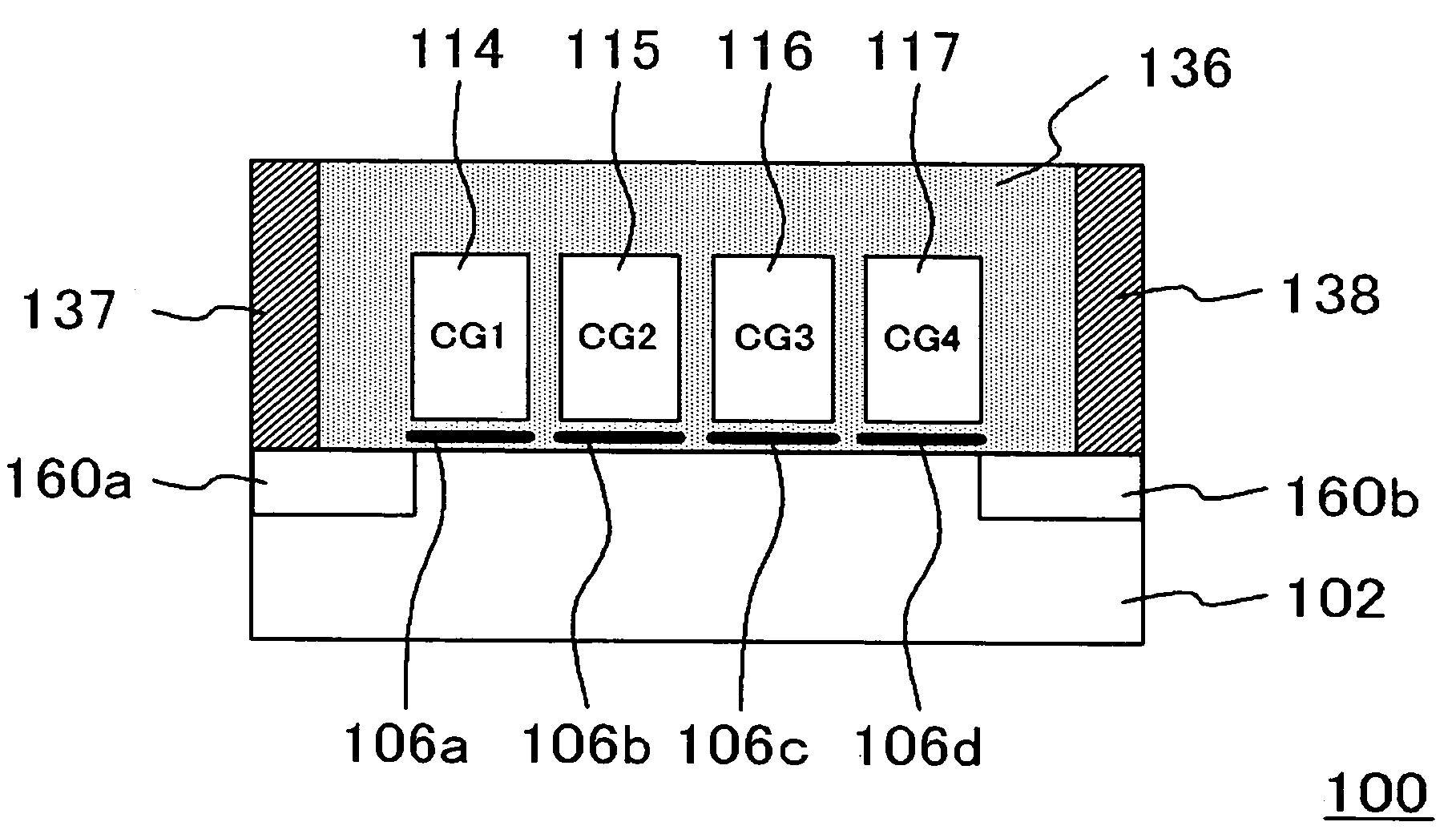
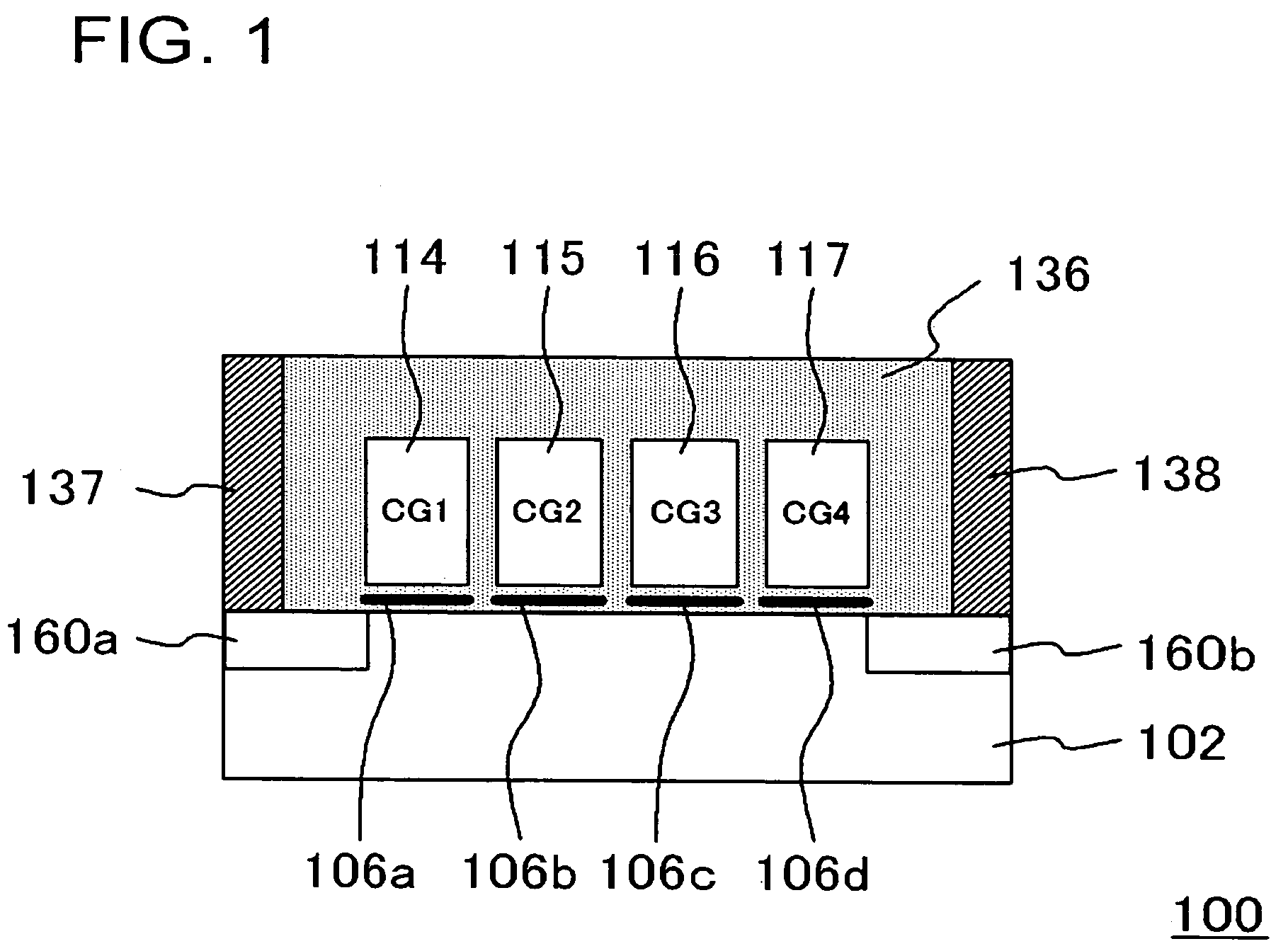
[0044]FIG. 1 is a cross-sectional view, showing a configuration of a nonvolatile memory device according to the present embodiment. In the present embodiment, a nonvolatile memory device 100 includes four memory regions 106a to 106d, and control gates 114 to 117 that are counterparts to these memory regions 106a to 106d, respectively, and further, four-bit data can b...


PUM


Abstract

Data is written to a nonvolatile memory device having a memory region of four bits or larger in one memory cell sandwiched by a source and a drain with an improved accuracy. The nonvolatile memory device 100 includes four control gates 114 to 117 provided between a first and a second impurity-diffused regions 106a and 160b that are provided separately from the semiconductor substrate, and a memory cell including memory regions 106a to 106d that are counterpart of the control gates. A method for controlling the nonvolatile memory device 100 includes classifying the four control gates 114 to 100 into two groups of right and left sides, and then, applying a lower voltage to an impurity-diffused region that is further from a target memory region for injecting an electron and applying a higher voltage to an impurity-diffused region that is closer the target memory region, and moreover applying a higher voltage, the higher voltage being higher than voltages applied to other control gates.

Description

[0001]This application is based on Japanese patent application No. 2005-206,711, the content of which is incorporated hereinto by reference.BACKGROUND[0002]1. Field of The Invention[0003]The present invention relates to a method for controlling a nonvolatile memory device having a memory region of four bits or larger in one memory cell sandwiched by a source and a drain.[0004]2. Related Art[0005]An NAND (not and) nonvolatile memory device having a plurality of memory regions and a plurality of counterpart control gates, which are all disposed between a source and a drain, is known in the conventional technology.[0006]A type of NAND cell that conducts writing data by utilizing tunneling current is disclosed by Masaki Momodomi et al., in “An Experimental 4-Mbit CMOS EEPROM with a NAND-Structured Cell”, IEEE Journal of solid-state circuits, vol. 24, No. 5, 1989, pp. 1238 to 1243, and is also disclosed in Japanese Patent Laid-Open No. H5-129,564 (1993). In Japanese Patent Laid-Open No. ...

Claims


Application Information

Patent Timeline
Patent Type & Authority Patents(United States)
IPC IPC(8): G11C11/34
CPCG11C16/0483H01L27/115G11C16/0466G11C16/10H10B69/00
Inventor YOSHINO, AKIRA
Owner RENESAS ELECTRONICS CORP
Why Eureka
Try Eureka