Disaster recovery with bounded data loss

a disaster recovery and data loss technology, applied in relational databases, database models, instruments, etc., can solve the problems of permanent loss of modifications and updates to the database after the last backup, more serious failures, and permanent loss of database modifications and updates, etc., to achieve the effect of improving performance over synchronous approaches

Active Publication Date: 2008-12-09
ORACLE INT CORP
View PDF9 Cites 52 Cited by
  • Summary
  • Abstract
  • Description
  • Claims
  • Application Information

AI Technical Summary

Benefits of technology

[0011]The present invention addresses this and other needs by allowing a database operator to set a bound that limits the number of transactions that can be lost. To improve performance over the synchronous approach, transactions are placed in a buffer to be sent to the standby system, but, to limit the data loss to a predetermined number of transactions, the transactions are synchronized based on the predetermined bound and on the number of transactions currently in the buffer. Because the predetermined bound is specified in terms of the number of transactions, the database operator can set a meaningful tradeoff between performance and data availability that is appropriate for the particular needs of the database operator's installation.

Problems solved by technology

Some failures are more serious, however.
For example, a hard disk can be unreadable after a head crash.
In these cases, the modifications and updates to the database after the last backup are permanently lost.
Moreover, restoration of a database from backups and redo logs is a time consuming process, and some organizations cannot afford the necessary downtime.
For example, an earthquake in San Francisco is unlikely to destroy a standby database in Boston.
The batch approach, however, incurs a high risk of data loss in case of a primary system 510 crash, because the archiver process 515 works in a batch mode to ship the redo records to the standby database system 530.
Moreover, it is difficult to characterize the amount of the data lost in terms that database owners can best understand.
The maximum exposure for loss of data in this approach is usually described in terms of the size of the redo logs, but this information is not helpful for database owners, who would rather want to know how many orders were lost.
Another way to characterize the amount of data lost is by time, for example, “within the last five minutes,” but this also would not tell the database owner how may sales orders were involved.
By contrast, the synchronous approach is capable of ensuring that the standby database records every committed transaction, i.e. with zero data loss, but at a substantial performance penalty.
This network latency is substantial and degrades performance for every transaction that the primary database 610 commits.
By contrast, the performance penalty of the batch approach is less severe, which typically incurs marginal additional overhead in terms of processing and disk input / output resources.

Method used


Image

  • Disaster recovery with bounded data loss
  • Disaster recovery with bounded data loss
  • Disaster recovery with bounded data loss

Examples


Embodiment Construction

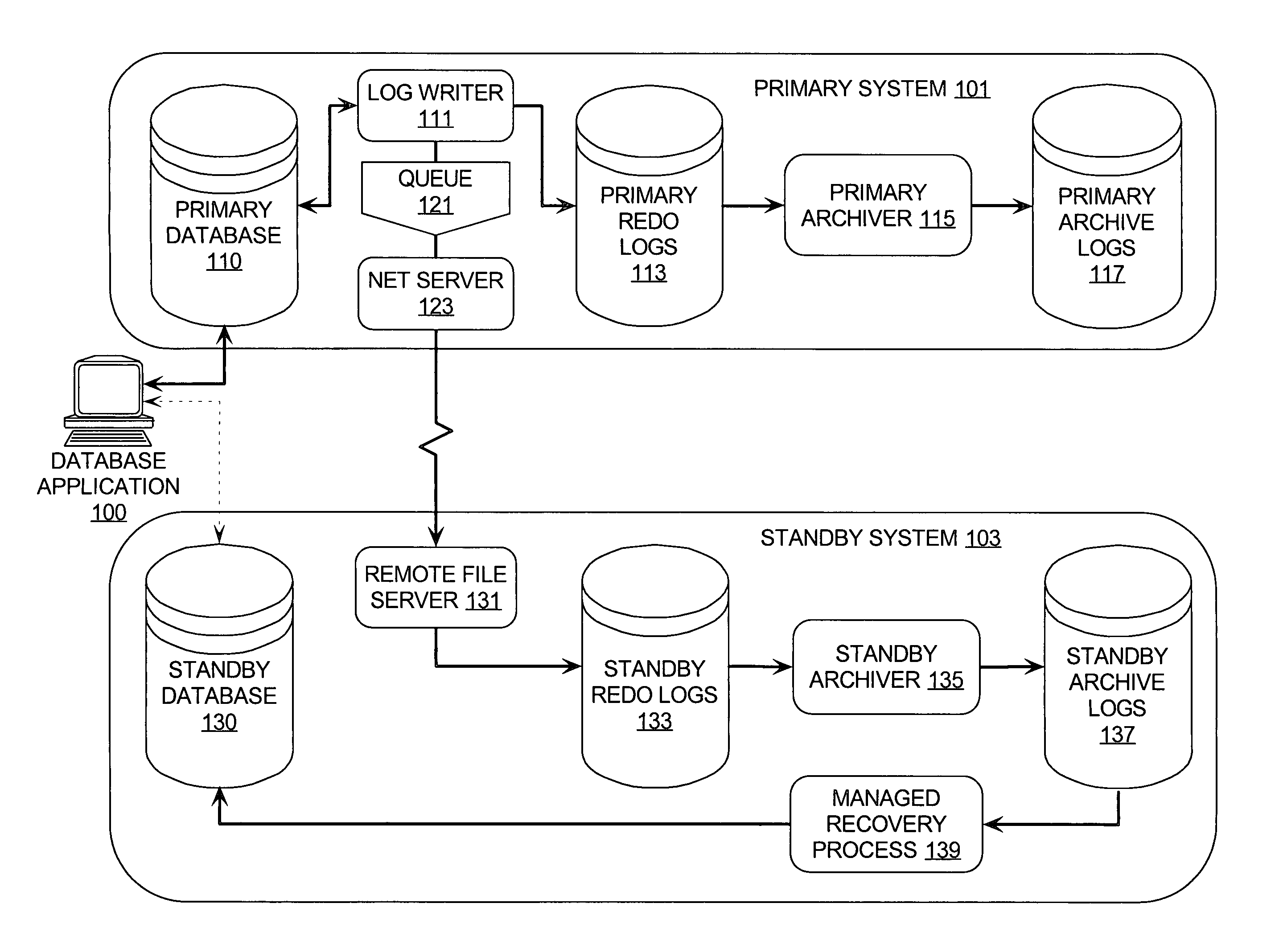
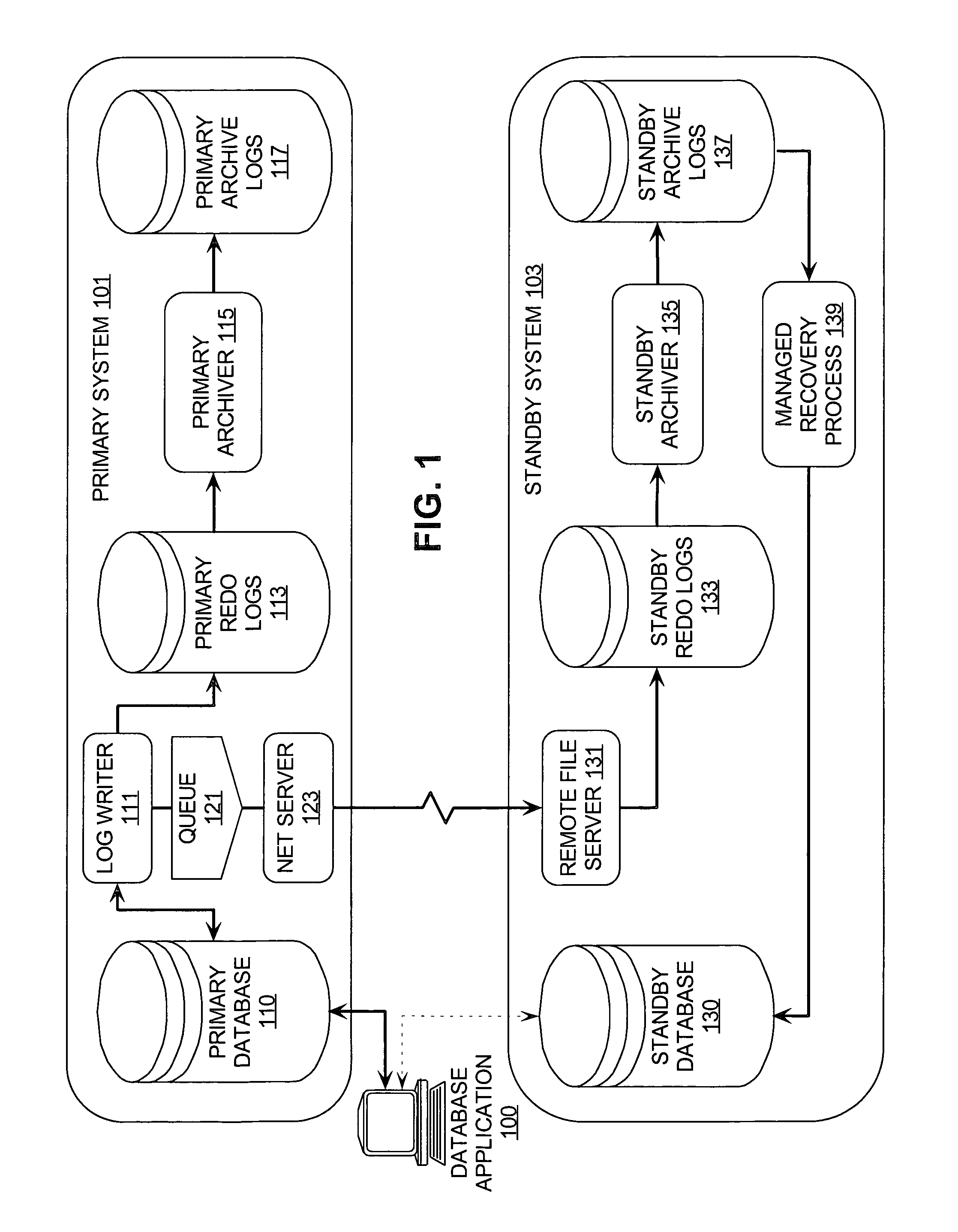
[0025]A system, method, and software for disaster recovery are described. In the following description, for the purposes of explanation, numerous specific details are set forth in order to provide a thorough understanding of the present invention. It is apparent, however, to one skilled in the art that the present invention may be practiced without these specific details or with an equivalent arrangement. In other instances, well-known structures and devices are shown in block diagram form in order to avoid unnecessarily obscuring the present invention.

[0026]In a database management system, data is stored in one or more data containers, each container contains records, and the data within each record is organized into one or more fields. In relational database systems, the data containers are referred to as tables, the records are referred to as rows, and the fields are referred to as columns. In object-oriented databases, the data containers are referred to as object classes, the r...


PUM


Abstract

A data recovery methodology with bound transaction data loss is described in which a database operator is allowed to set a bound that limits the number of transactions that can be lost. Transactions are placed in a buffer to be sent asynchronously to the standby system and synchronized based on the predetermined bound and on the number of transactions currently in the buffer.

Description

FIELD OF THE INVENTION[0001]The present invention relates to database systems and more particularly to providing disaster recovery with a bounded data loss.BACKGROUND OF THE INVENTION[0002]Organizations use computer databases to store, organize, and analyze some of their most important information. For example, a business may employ a database to warehouse its sales and ordering information so that analysts can predict trends in product sales or perform other kinds of data mining for long-range planning. Because database systems are responsible for managing information vital to the organization's operation, it is crucial for mission-critical database systems to implement mechanisms for recovery following a database system failure.[0003]Recovery from all but the most serious kinds of failures generally relies on periodic backups, which are done to save the state of the database to a longer term storage medium, such as magnetic tape or optical disk. Because users continue to modify th...

Claims


Application Information

Patent Timeline
Patent Type & Authority Patents(United States)
IPC IPC(8): G06F17/30
CPCG06F11/2074G06F17/30595G06F17/30575G06F11/1471G06F11/1474G06F16/27G06F16/284
Inventor GIRKAR, MAHESHANDERSON, RICHARD J.LEE, STEVEKUNDU, JOYDIP
Owner ORACLE INT CORP
Why Eureka
Try Eureka