Sensor system for measuring an electric potential signal of an object

a technology of electric potential and sensor system, which is applied in the field of measuring an electric potential signal, can solve the problems of large changes in the output signal produced by the sensor, the behavior of static electric potential in the capacitive measurement, and the degradation of almost all capacitive measurements in real world environments, so as to reduce the noise of artifacts, reduce the amount of artifacts measured, and reduce the effect of artifact signals

Active Publication Date: 2008-12-16
QUANTUM APPLIED SCI & RES
View PDF17 Cites 15 Cited by
  • Summary
  • Abstract
  • Description
  • Claims
  • Application Information

AI Technical Summary

Benefits of technology

[0015]The invention generally pertains to reducing artifact noise signals that are generally present when non-invasive capacitive type measurements are taken of a body. More specifically, the invention pertains to reducing the artifact signals measured by a capacitive sensor when the sensor is operated in a static electric field produced by an object of interest. According to a first preferred embodiment of the invention, a given artifact signal can be reduced by minimizing the potential difference between a sensor circuit ground point and the potential of the object. According to a second preferred embodiment of the invention, the change in signal due to the sensor's motion in the field produced by the object is minimized by reducing the impact of changes in coupling to the signal source.
[0016]The invention generally includes a sensor system for measuring an electric potential signal generated by an object. A first signal sensor is provided including a capacitive-type electrode and an amplifier with a DC supply, a local ground connection, an input connected to the capacitive-type electrode and an output sending a signal. A second signal sensor is provided including a capacitive-type electrode and an amplifier with a DC supply, a local ground connection, an input connected to the capacitive-type electrode and an output sending a signal. A differential amplifier, including a first input connected to the output of the first signal sensor and a second input connected to the output of the second signal sensor, has an output sending a signal of interest proportional to the difference between the signal of the first signal sensor and the signal of the second signal sensor. Processing circuitry includes an input connected to the output of the differential amplifier and a local ground connection. A ground sensor includes a first ground electrode, a second ground electrode, and an amplifier with a DC supply. A ground connection is attached to the first ground electrode and a universal ground. An input is connected to the second ground electrode and an output is connected to the ground connection of the amplifier of the first signal sensor and the amplifier of the second electrode. By this arrangement, a voltage present at the local ground connections of the first and second signal sensors is forced to be the same as the voltage present at the second ground electrode so as to reduce an effect of a change in static potential on the signal of interest.
[0017]In another embodiment, a capacitor is inserted in series between the electrode and the amplifier of the first signal sensor, while the electrode of the first signal sensor and the body are separated by a relatively large distance. In yet another embodiment, the electrode of the first signal sensor and the body are connected by an electrically conducting fluid. In a still further embodiment, a feedback network including an amplifier and a series capacitor are included. The gain of the amplifier in the feedback circuit is set to 1 plus the input capacitance of the high impedance amplifier connected to the electrode, including other stray capacitances in the system, divided by the value of the series capacitor of the feedback network. Such an arrangement will produce a negative capacitance that will compensate for not only the capacitance between the amplifier and ground but also other stray capacitance present in the system.

Problems solved by technology

While the system set forth in the '800 patent is effective, almost all capacitive measurements that occur in real world environments are degraded by artifact signals and noise caused by the presence of static electric fields.
An important limiting factor in capacitive measurements is the behavior of static electric potential in the region where sensors must be located to measure a signal of interest.
Such changes in the sensed potential can saturate the capacitive electrode causing large changes in the output signal produced by the sensor.
Such artifact signals can often be very similar in frequency to the signal of interest and thus are typically very difficult to filter.
In the case of a sensed bioelectric signal, certain artifact signals, such as common mode signals, can be particularly troublesome.
The opposite is also true and can lead to measuring equipment reading an irregular heartbeat or fibrillation when the heartbeat is actually normal.
However, no simple way of eliminating such signals is proposed.
Since, by its very nature, a non-invasive capacitive measurement system cannot make a resistive coupled electric contact with an object, in such a system, a static potential cannot be reduced in this manner.
However, this approach is limited by how similar the potential of the sensing system is to the static potential of the object.
Such an approach works relatively well for conventional skin contact resistive electrodes but does not work so well for capacitive electrodes, particularly ones that are not firmly attached to the body.
This type of measurement would be limited by the unknown variations in the coupling of each sensor to the static potential, the calibration precision of the sensor components, and the dynamic range of the differencing system.
However, the unknown variations of the coupling of each sensor is a fundamental problem for capacitors in a static electric field.
However, such an approach is not compatible with non-invasive measuring.
For example, such a technique would not work with sensors located in clothing.
There is inherently a lack of precision and repeatability in the coupling efficiency of a capacitive sensor to the static potential due to changes in the capacitance electrode that couples to the potential.

Method used


Image

  • Sensor system for measuring an electric potential signal of an object
  • Sensor system for measuring an electric potential signal of an object
  • Sensor system for measuring an electric potential signal of an object

Examples


Embodiment Construction

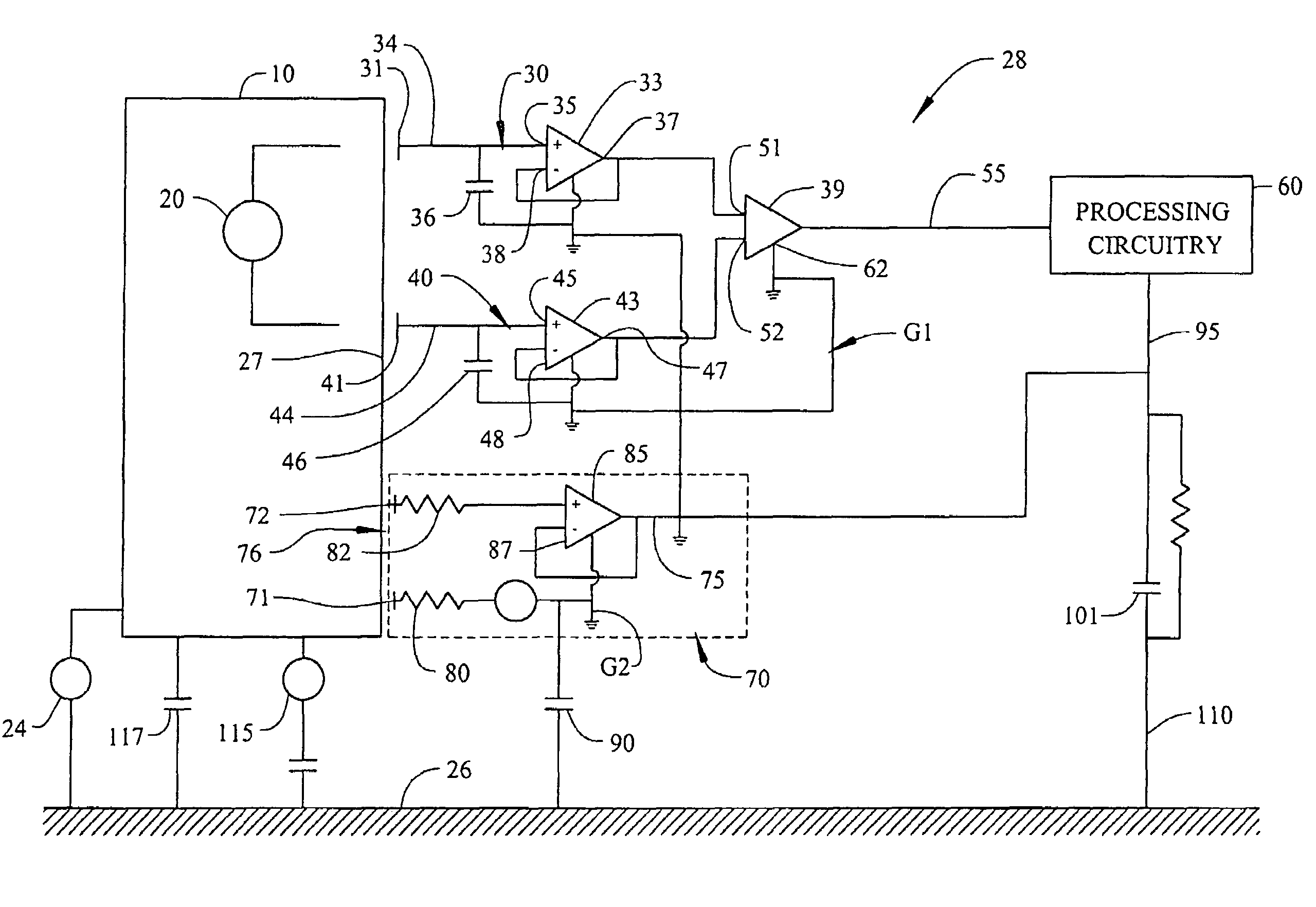
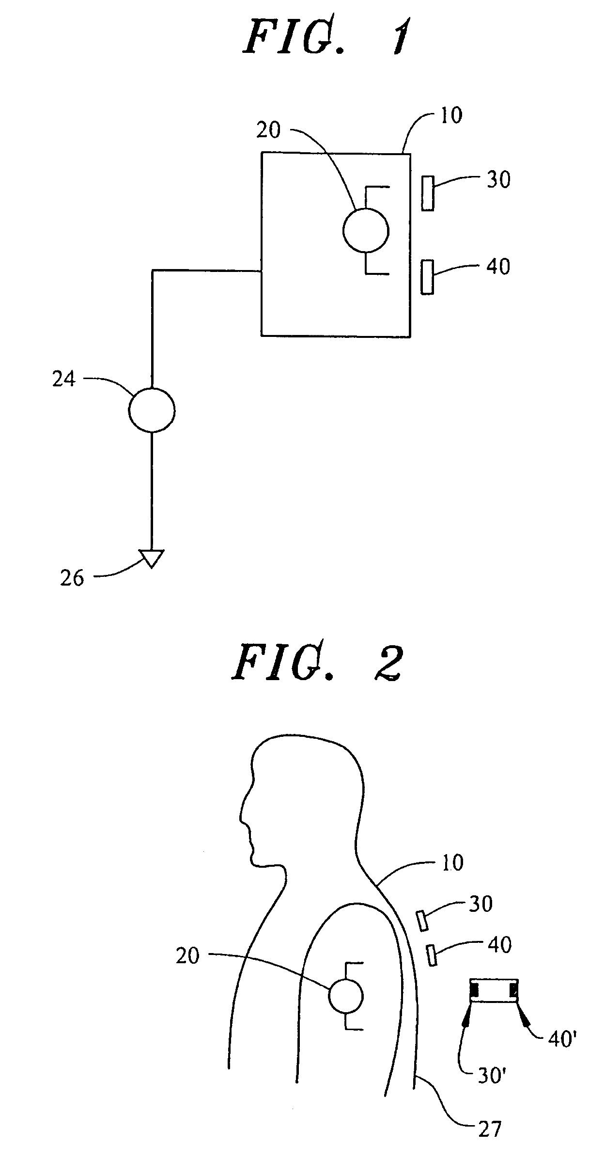
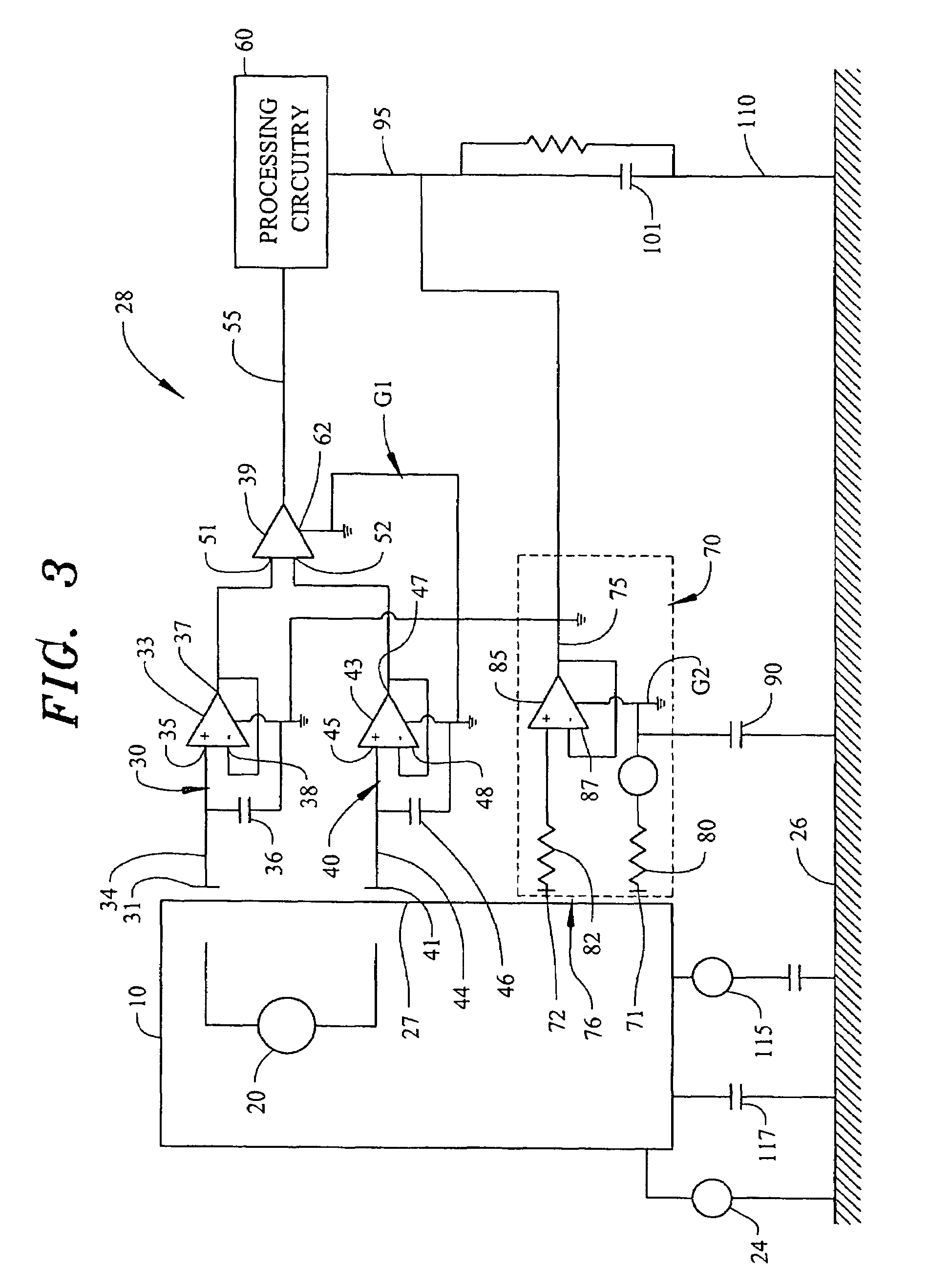
[0029]The overall system for measuring a signal can be generally discussed with reference to FIG. 1. An object or body 10 has a source 20 of alternating current type voltage located therein. This voltage source 20 produces a voltage signal of interest that is to be measured. Object 10 is large compared to the spatial variation of the signal of interest produced by voltage source 20. Object 10 is charged to a static potential 24 relative to a distant point which we will define as a ground 26 having a voltage or potential of zero. The conductivity of object 10 is such that the static potential 24 at its surface 27 is substantially uniform compared to the spatial variation of the signal of interest. Further, object 10 maintains this spatial uniformity over the timescales of interest even when the static potential 24 suddenly changes. An example of such an object would be an aircraft, a human body, or a partly conducting shield placed over a sensor to protect it from the environment. So...


PUM


Abstract

The invention generally pertains to reducing artifact noise signals present when non-invasive capacitive-type signal measurements are taken of static electric fields produced by an object of interest. According to a first preferred embodiment of the invention, a given static artifact signal is reduced by minimizing the potential difference between a ground point of sensor circuitry and the potential of the object. According to a second preferred embodiment of the invention, the change in signal due to motion of the sensor in the field produced by the object is minimized by reducing the impact of changes in coupling to the signal source.

Description

CROSS-REFERENCE TO RELATED APPLICATION[0001]The present application represents a National Stage application of PCT / US2005 / 023606 filed Jul. 1, 2005 entitled “A Sensor System for Measuring an Electric Potential Signal of an Object”, and claims the benefit of U.S. Provisional Patent Application Ser. No. 60 / 584,146 filed Jul. 1, 2004 entitled “Method to Reduce the Effect of Static Potentials in Capacitive Measurements.STATEMENT OF GOVERNMENT INTEREST[0002]The United States Government retains a royalty fee, fully paid up, non-exclusive license to make, use, have made, or have the invention used for governmental purposes.BACKGROUND OF THE INVENTION[0003]1. Field of the Invention[0004]The present invention pertains to measuring an electric potential signal generated by an object and, more particularly, to reducing the effect of artifact signals or signals caused by a change in static potential on measurement of an electric potential signal of interest.[0005]2. Discussion of the Prior Art[...

Claims


Application Information

Patent Timeline
Patent Type & Authority Patents(United States)
IPC IPC(8): G01R27/26
CPCA61B5/0408A61B5/04284A61B5/0478G01R29/12A61B5/25A61B5/302A61B5/291
Inventor FRIDMAN, IGORHERVIEUX, PAULKUNSTMANAS, LINASMATTHEWS, ROBERT
Owner QUANTUM APPLIED SCI & RES
Why Eureka
Try Eureka