Integrated security system having network enabled access control and interface devices

a security system and network enabled technology, applied in the field of security systems, can solve the problems of ineconomical replacement of hardware, complicated operation of new features of conventional systems, and inability to interoperate with installed legacy systems, and achieve the effect of reducing software maintenance, training, support and installation costs

Inactive Publication Date: 2008-12-16
CARRIER FIRE & SECURITY AMERCIAS CORP
View PDF18 Cites 51 Cited by
  • Summary
  • Abstract
  • Description
  • Claims
  • Application Information

AI Technical Summary

Benefits of technology

[0014]In one embodiment, an extensible markup language, XML, is used to represent predetermined resource information and global events transmitted between the network security controller and the network nodes. In another embodiment, a security system administrative user can access the security system using a standard web browser that operates on a

Problems solved by technology

The installation, the addition of new features and the operation of conventional systems is often complicated by the use of various incompatible communications channels required by the individual systems.
Another problem, relating to the addition of new features, is the interoperability of installed legacy systems where hardware replacement is not economically feasible.
Managing the configuration of hardware devices at the lowest levels of the system, for example card readers door switches and motion sensing devices is complicated by the requirement for continued operation during software upgrades and the need to operate with various hardware devices including legacy reader modules, input modules, output modules, and panels (i.e., intelligent devices which control a collection of modules).
The addition of new user interfaces and remote interaction with the security monitoring application is difficult with the configuration of FIG. 1 because typically a single application operates on the dedicated monitoring station 14.
It is further difficult for the panels 18 to interoperate with devices using newer technol

Method used


Image

  • Integrated security system having network enabled access control and interface devices
  • Integrated security system having network enabled access control and interface devices
  • Integrated security system having network enabled access control and interface devices

Examples


Embodiment Construction

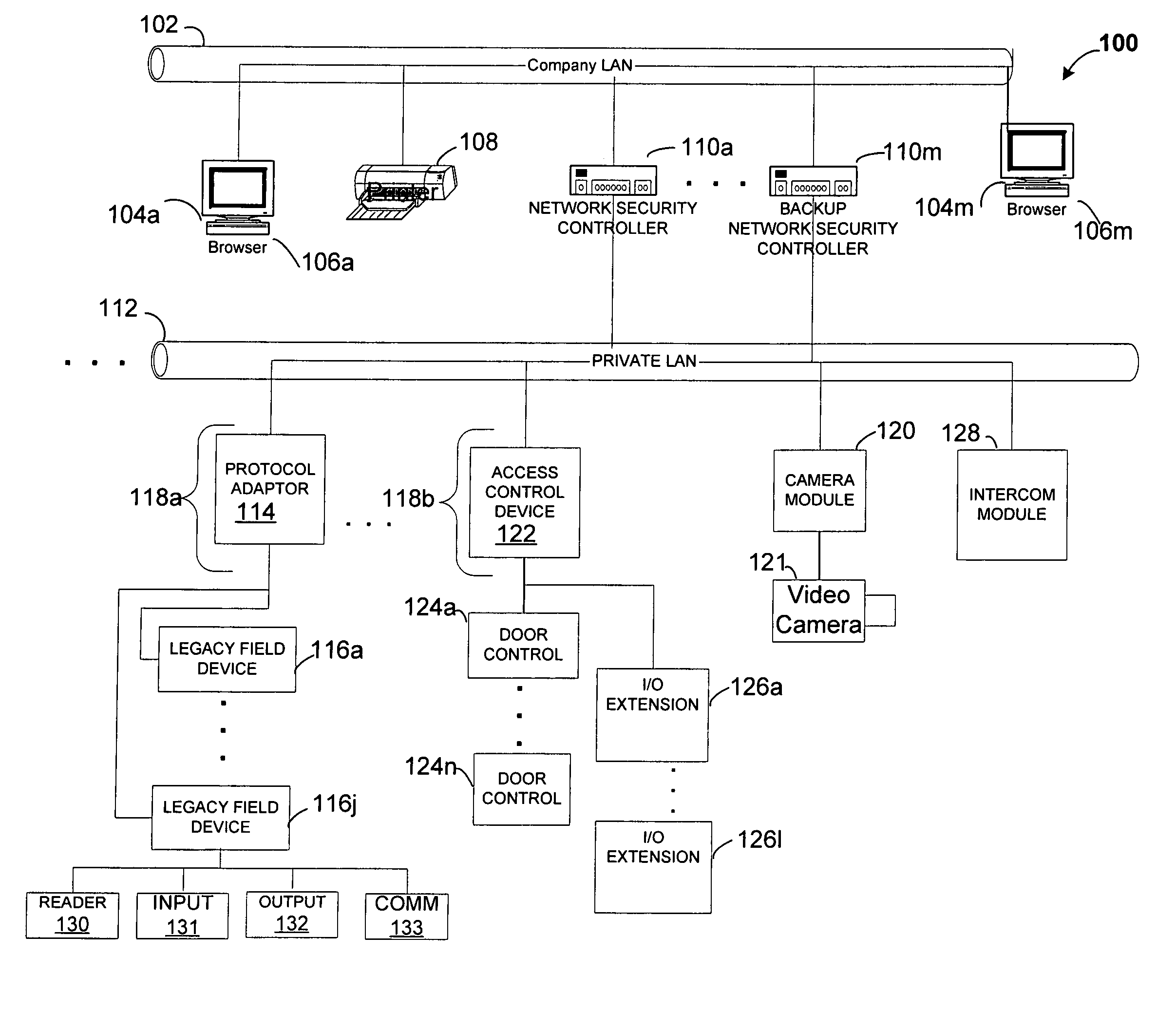
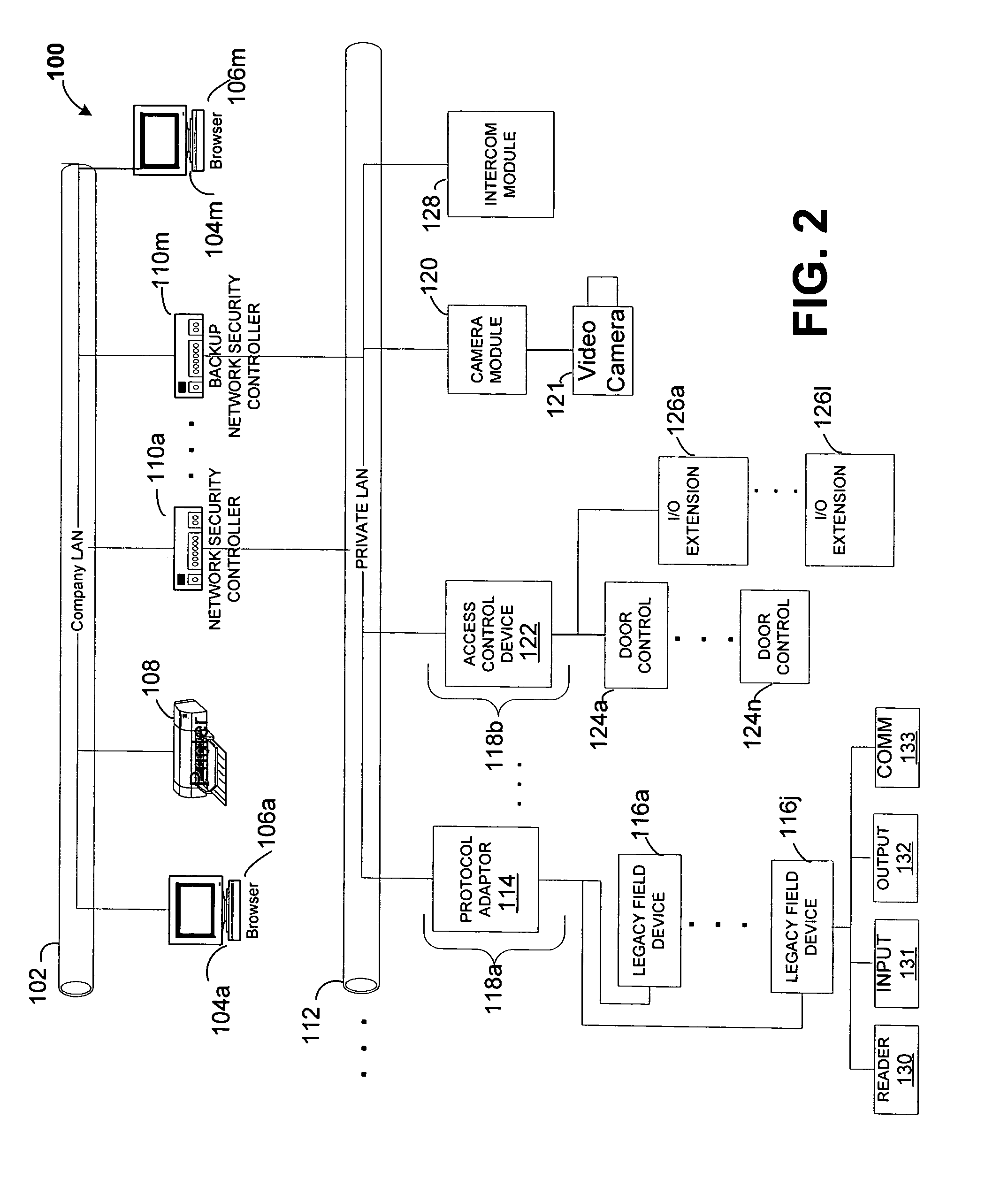
[0024]Before providing a detailed description of the invention, it may be helpful to define some of the terms used in the description. The term “network enabled” as used herein refers to a device (also referred to as a module) or system which communicates over network media using an open system transport and data protocol, for example the TCP / IP protocol over a variety of physical media, including but not limited to CSMA / CD (Carrier Sense Multiple Access LANs with Collision Detection) Ethernet IEEE 802.3, Wi-FI Wireless LAN IEEE 802.11, Wireless Personal Area Network IEEE 802.15, Broadband Wireless Access IEEE 802.16, Broadband, HomePlug® and HomePNA™ networks.

[0025]As used herein, the term “portal” also referred to as “access portal” refers to a physical opening or area under access control and / or supervision. A security system permits or denies physical access between the low security (e.g., outside an office) and high security side of the portal. The term “access point” as used h...


PUM


Abstract

An integrated security system operating over a network includes a network security controller coupled to the network having a relational database including portal objects and related resources represented in at least one table in the relational database. The system further includes at least one network node having a local database coupled to the network adapted to receive predetermined resource information from the relational database, an event generator coupled to the local database to provide at least one portal event in response to the predetermined resource information received by the local database, and a finite state portal controller coupled to the network and the event generator for providing at least one of an action and a global event in response to the at least one portal event.

Description

CROSS-REFERENCE TO RELATED APPLICATIONS[0001]This application claims the benefit of U.S. Provisional Application No. 60 / 447,544, filed on Feb. 14, 2003 which application is hereby incorporated herein by reference in its entirety.STATEMENTS REGARDING FEDERALLY SPONSORED RESEARCH[0002]Not applicable.FIELD OF THE INVENTION[0003]This invention relates generally to security systems and more particularly to security systems including network enabled access control, video and audio devices which communicate over a common local area network.BACKGROUND OF THE INVENTION[0004]In security applications, separate systems are often needed to provide access control, burglar alarm, and audio and video capabilities at access points in an individual office or a facility including one or more buildings. The installation, the addition of new features and the operation of conventional systems is often complicated by the use of various incompatible communications channels required by the individual system...

Claims


Application Information

Patent Timeline
IPC IPC(8): G06F17/30G06F15/18H04L9/00
CPCG07C9/00166G08B13/19656G08B25/08G07C9/00103G08B25/003G07C9/27G07C9/38
Inventor MOSS, JOHN L.GAIMAN, BARRY
Owner CARRIER FIRE & SECURITY AMERCIAS CORP
Why Eureka
Try Eureka