Structure comprising an adiabatic coupler for adiabatic coupling of light between two optical waveguides and method for manufacturing such a structure
a technology of adiabatic coupling and optical waveguide, which is applied in the field of integrated optics, can solve the problems of high coupling loss, difficult to realize continuous changes in layer thickness along the propagation direction, and much more difficult manipulation of waveguide thickness h, etc., and achieves the effect of easy post-processing
- Summary
- Abstract
- Description
- Claims
- Application Information
AI Technical Summary
Benefits of technology
Problems solved by technology
Method used
Image
Examples
example
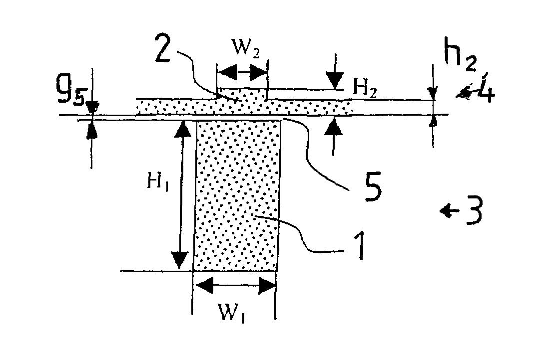
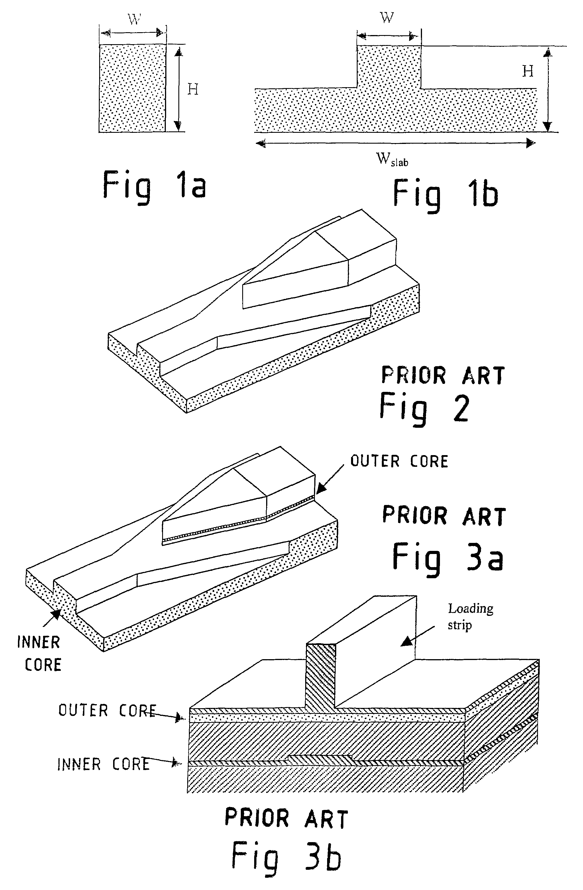
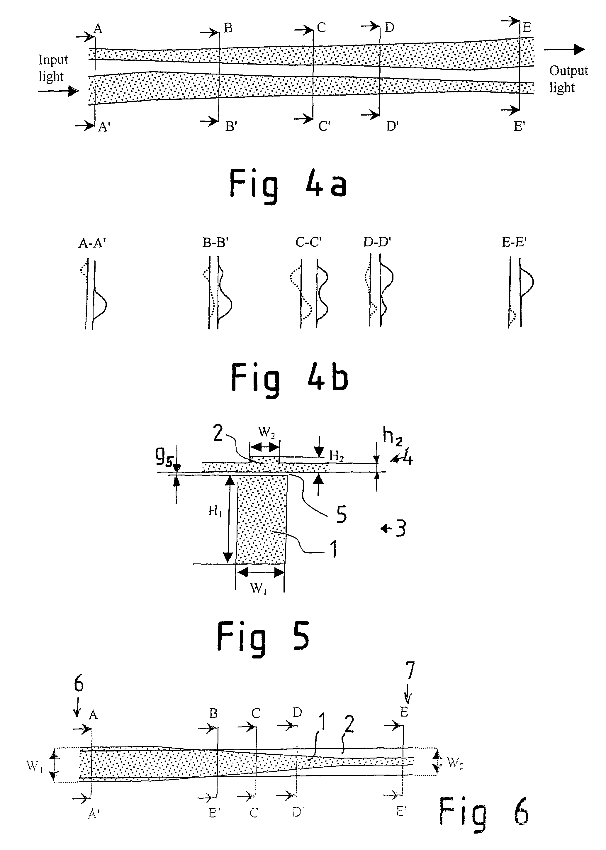
[0093]The operation of a coupling structure according to the invention was simulated with full-vectorial modal analysis by using a commercial TempSelene software. In the simulation the following parameters and dimensions were used: TE polarization, calculation area 8×12 μm2 (64×512 points), λ=1550 nm, H1=8 μm, H2=3 μm, h2=1.5 μm, W2=3 μm, and g5=50 nm. Furthermore, the refractive index was 3.5 (silicon) for both waveguide cores, 1.5 (oxide) for a thin buffer layer on top of the inner waveguide 1 filling the separating gap 5, and 1 (air) for the surrounding background material. Along the adiabatic coupling structure the width W1 of the lower waveguide core was changed from 3 to 2.8 μm.
[0094]FIG. 11 presents the simulated intensity distribution of the fundamental TE mode in different cross-sections of the adiabatic coupling structure. It clearly demonstrates the coupling of light from the inner waveguide to the outer waveguide. Further off from the range W1=3-2.8 μm, practically all t...
PUM
 Abstract
Description
Claims
Application Information
 - R&D
- Intellectual Property
- Life Sciences
- Materials
- Tech Scout
- Unparalleled Data Quality
- Higher Quality Content
- 60% Fewer Hallucinations
Browse by: Latest US Patents, China's latest patents, Technical Efficacy Thesaurus, Application Domain, Technology Topic, Popular Technical Reports.
© 2025 PatSnap. All rights reserved.Legal|Privacy policy|Modern Slavery Act Transparency Statement|Sitemap|About US| Contact US: help@patsnap.com


