Gas sensor

a technology of gas sensors and sensors, applied in the field of gas sensors, can solve the problems of prolonging the life of the elements and prolonging the life of the gas sensors, and achieve the effect of preventing sensitivity lowering

Active Publication Date: 2009-01-20
RIKEN KEIKI KK
View PDF30 Cites 35 Cited by
  • Summary
  • Abstract
  • Description
  • Claims
  • Application Information

AI Technical Summary

Benefits of technology

[0017]While the water-repelling filter prevents the moisture in the specimen gas passage from entering the gas-sensing chamber, the heater directly heats the specimen gas introduced from the specimen gas intake into the gas-sensing chamber. These provisions prevent the adherence of condensed water to the sensing element, thereby preventing sensitivity lowering and element breakdown and, as a result, prolonging the life of the elements.
[0019]While the water-repelling filter prevents the moisture in the specimen gas passage from entering the gas-sensing chamber, the porous metal sheet prevents the sensing element from getting wetted. These provisions prevent element breakdown and sensitivity lowering and prolong the life of the gas sensor.
[0021]The heater directly heats the specimen gas introduced into the gas-sensing chamber through the specimen gas intake and prevents sensitivity lowering.

Problems solved by technology

These provisions prevent the adherence of condensed water to the sensing element, thereby preventing sensitivity lowering and element breakdown and, as a result, prolonging the life of the elements.
These provisions prevent element breakdown and sensitivity lowering and prolong the life of the gas sensor.

Method used


Image

  • Gas sensor
  • Gas sensor
  • Gas sensor

Examples


first embodiment

[0042]Now details of this invention will be described by reference to the illustrated embodiments.

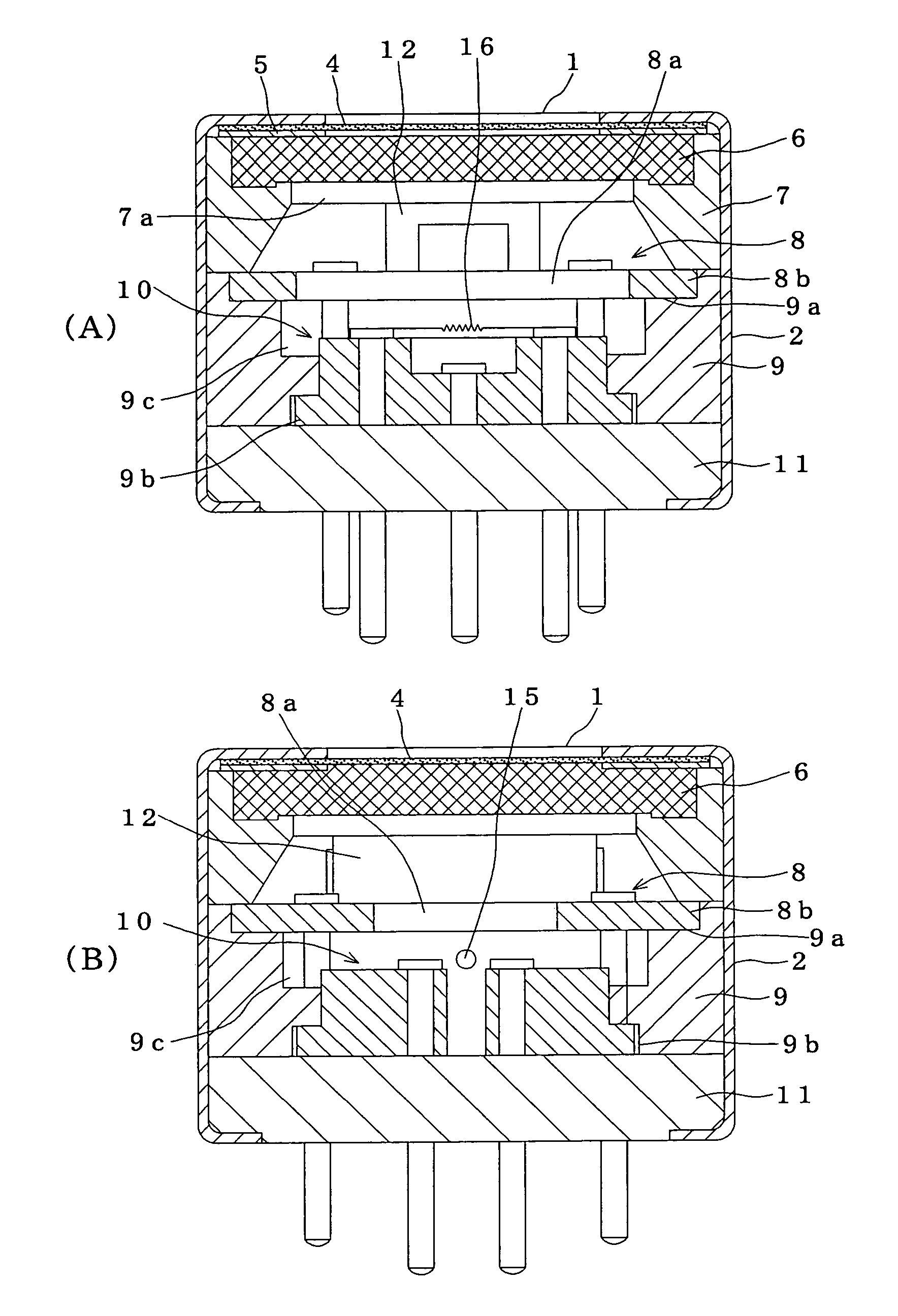
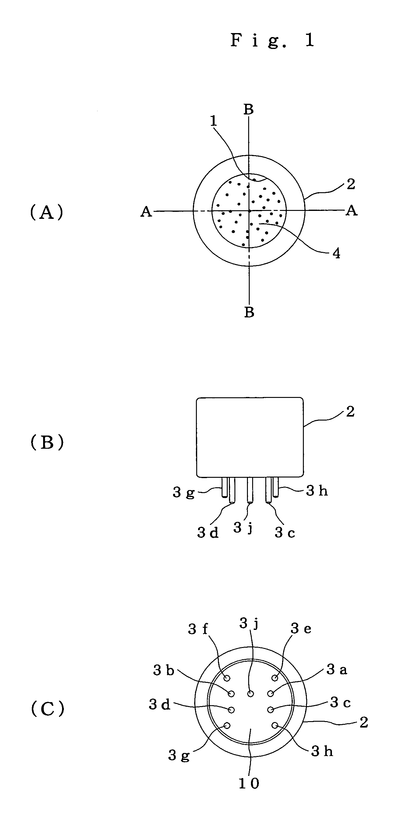
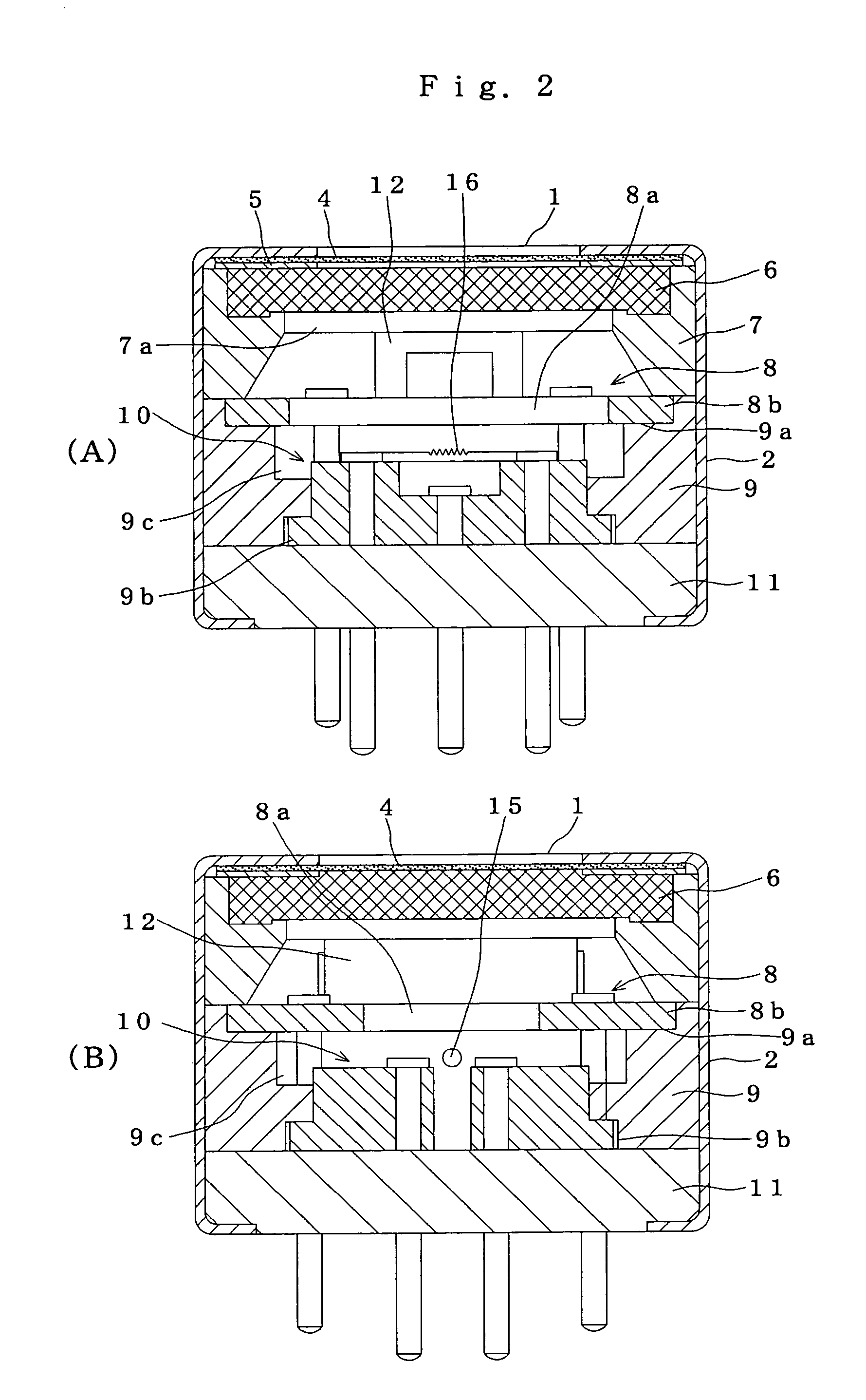
[0043]FIGS. 1 and 2 show a first embodiment of the gas sensor according to this invention. A case 2 has a specimen gas intake 1 at one end thereof and lead pins 3a to 3h for connection at the other end thereof. The case 2 holds a water-repelling filter 4, a packing 5, a sintered porous metal sheet 6, a first spacer 7, a heating unit 8, a second spacer 9, a gas-sensing unit 10, and a base plate 11 stacked in that order from the side of the specimen gas intake 1. The other end of the case 2 is constricted and fastened so that the connection lead pins 3a to 3h and a positioning pin 3j from the gas-sensing unit 10 are pulled out.

[0044]The water-repelling filter 4 is made of a porous Teflon (registered trade mark) resin that prevents the ingress of liquid and dust. The sintered porous metal sheet 6 is made by sintering metal particles into a porous sheet.

[0045]The first spacer 7 supports the...

fifth embodiment

of the Heater

[0088]In the embodiment shown in FIGS. 15(A) to (C), paired heaters 46D lying along the surface of the base 38 are disposed on the outside of the sensing element 39 and temperature-compensating element 40. That is, the sensing element 39 and temperature-compensating element 40 are disposed between the paired heaters 46D at equal distance there from. The two rectangular heaters 46D, with the heat-release surfaces 49D thereof facing toward the specimen gas intake 35, heat the gas-sensing chamber 34. Reference numeral 48D denotes the leadwire of the heater 46D.

[0089]This embodiment also prolongs the life of the sensing element 39 by directly heating the inside of the gas-sensing chamber 34 with the heaters 46D in the same manner as the above-described embodiments. In particular, the heaters 46D that can be mounted on the base together with the sensing element 39 and temperature-compensating element 40 facilitate the supporting of the heaters 46D and manufacturing of the sa...

second embodiment

of the Specimen Gas Intake

[0094]In a hydrogen sensor 25 shown in FIG. 16, the sintered porous metal sheet 43 and the water-repelling filter 44 of, for example, polytetrafluoroethylene are fitted to the specimen gas intake 35 from within the gas-sensing chamber 34 in such a manner as to close the intake. The sintered porous metal sheet 43 and water-repelling filter 44 are fitted from within the flange 33. The water-repelling filter 44 having a thickness of 150 μm to 300 μm blocks the passage of water droplets while permitting the passage of water vapor.

[0095]This embodiment is characterized in that the specimen gas intake 35 protrudes to the inside of the exit passage 24. That is, the cylindrical segment 32 and cylindrical wall 45 are formed so that the specimen gas intake 35 inclines downward toward the downstream of the flow (indicated by the arrow A) of the off-gas in the exit passage 24.

[0096]The sintered porous metal sheet 43 and water-repelling filter 44 fitted to the specimen ...


PUM

PropertyMeasurementUnit
temperatureaaaaaaaaaa
thicknessaaaaaaaaaa
thicknessaaaaaaaaaa

Abstract

A hydrogen sensor 25 has a fitting base plate 29 in which a gas-sensing chamber 34 is formed, a specimen gas intake 35 formed on said fitting base plate 29, opening toward an exit passage 24 and introducing hydrogen gas into the gas-sensing chamber 34, a gas-sensing element 39 held in the gas-sensing chamber 34 and adapted to sense hydrogen gas, and a water-repelling filter 44 covering the specimen gas intake 35.

Description

TECHNICAL FIELD [0001]This invention relates to gas sensors for use in highly humid environments, and more particularly to the water-repelling and drip-proof structures of such gas sensors.BACKGROUND TECHNOLOGY [0002]For example, a solid polymer membrane type fuel battery has a stack of multiple cells each of which consists of a membrane of solid polyelectrolyte held between an anode and a cathode. While hydrogen is supplied as a fuel to the anode, air is supplied as an oxidizer to the cathode. Hydrogen ions generated by the catalytic reaction at the anode move through the film of solid polyelectrolyte to the cathode where an electrochemical reaction between the hydrogen ions and oxygen generates electricity.[0003]Fuel batteries like the aforesaid solid polymer membrane type fuel battery generally discharge the unreacted air (hereinafter referred to as the off-gas)to outside the system. Then, it is necessary to confirm that hydrogen gas is not present in the off-gas.[0004]Therefore,...

Claims


Application Information

Patent Timeline
Patent Type & Authority Patents(United States)
IPC IPC(8): G01N31/12G01N27/16G01N33/00H01M8/06H01M8/10
CPCG01N27/16H01M8/0662G01N33/005Y10T436/22H01M2300/0082Y02E60/50H01M8/10
Inventor OTANI, SEIICHINAKAMURA, YUKIOFURUSATO, MAMORU
Owner RIKEN KEIKI KK
Why Eureka
Try Eureka