

Thin film deposition device using an FTIR gas analyzer for mixed gas supply
- Summary
- Abstract
- Description
- Claims
- Application Information
AI Technical Summary
Benefits of technology
Problems solved by technology
Method used
Image

Examples
Embodiment Construction
[0030]The following description is provided to enable any person skilled in the art to make and use the invention and sets forth the best modes contemplated by the inventors of carrying out their invention. Various modifications, however, will remain readily apparent to those skilled in the art, since the general principles of the present invention have been defined herein to specifically provide a thin film deposition process and device with measurements of the depositing gases made in either the gas mixing chamber or the reaction chamber.
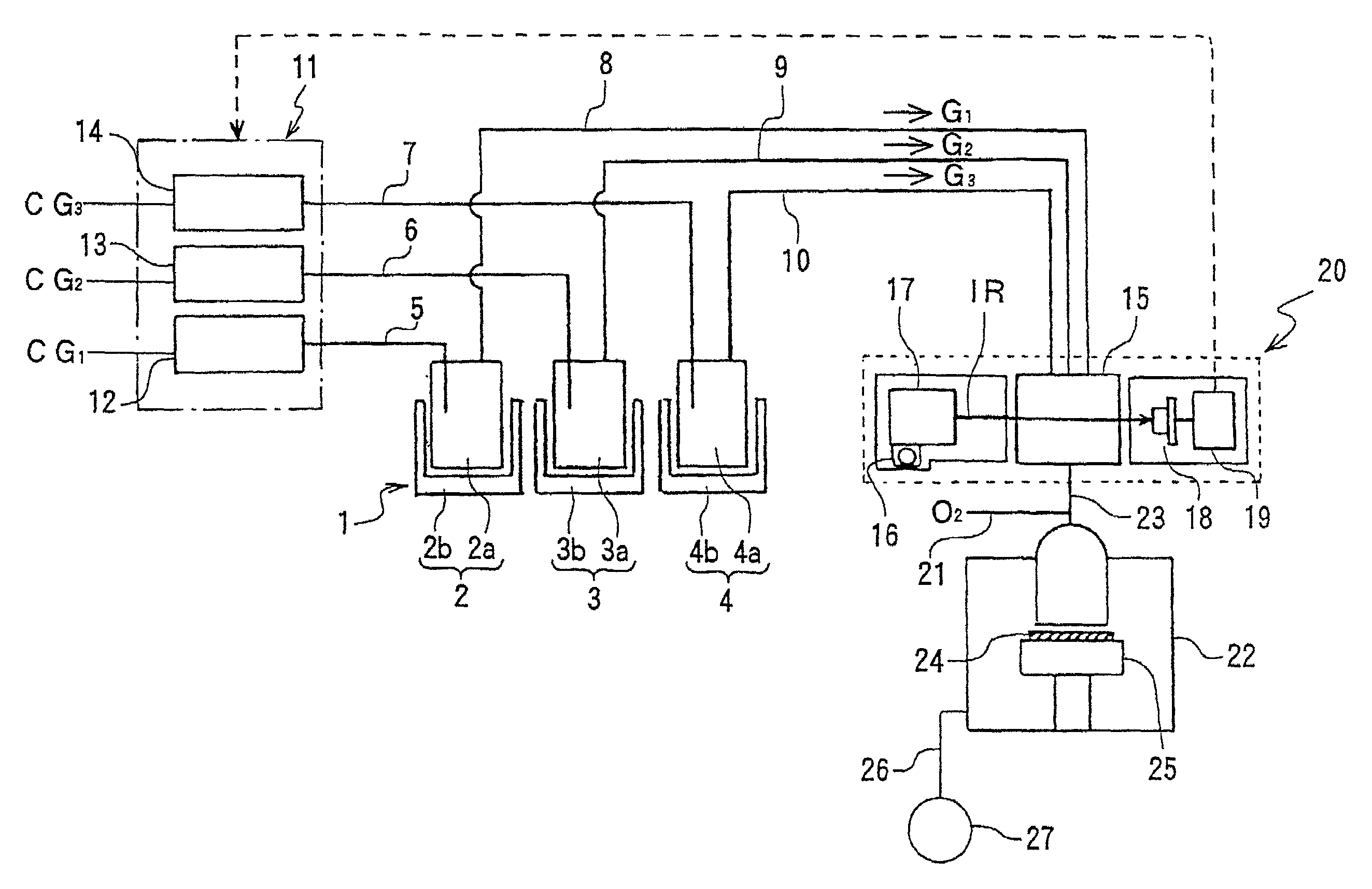
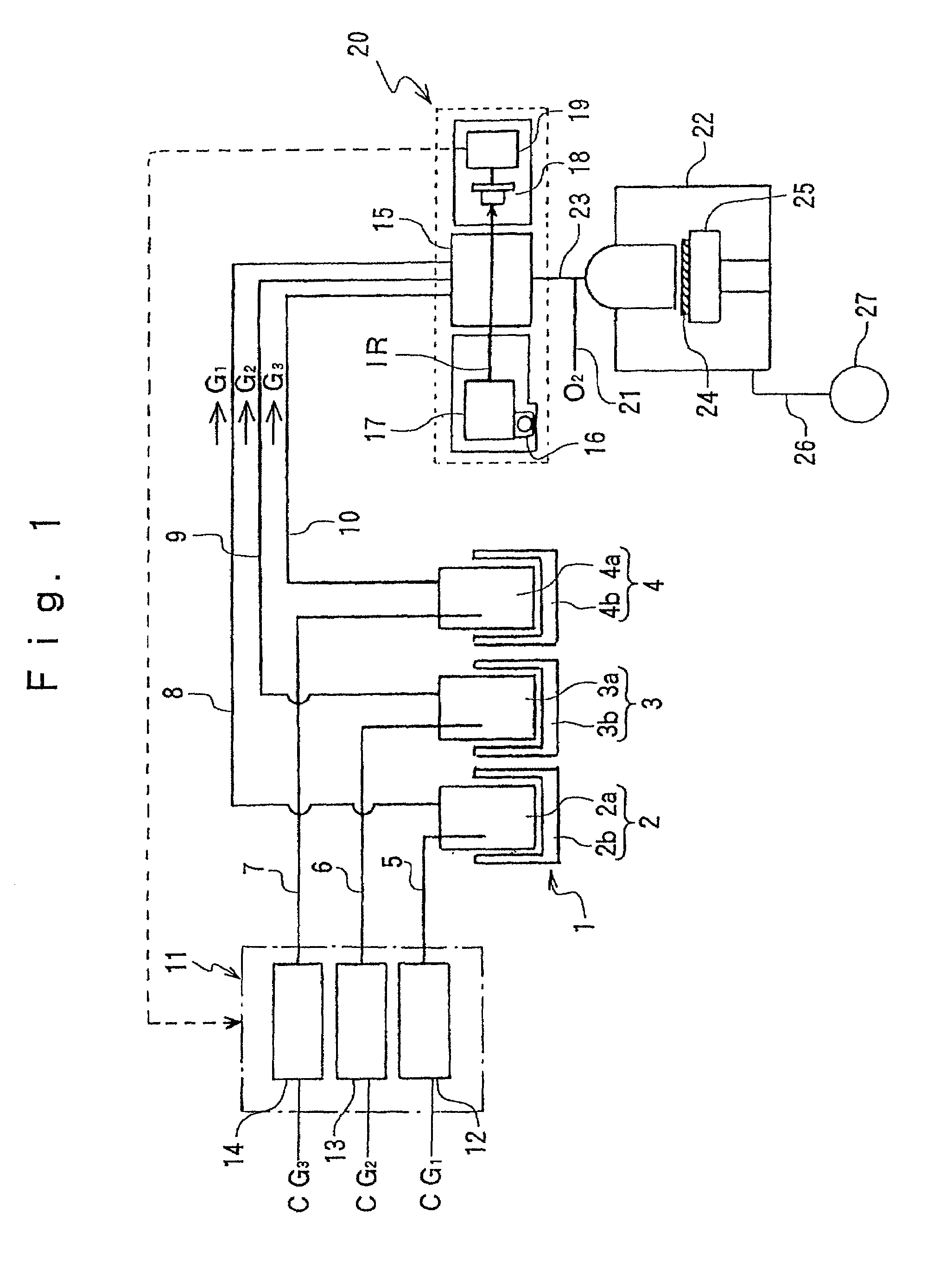
[0031]Referring to the drawings, embodiments of the present invention will be described. FIGS. 1-6 are related to a first embodiment of the present invention. FIG. 1 is a schematic view of one example of a thin film deposition device (MOCVD device) for carrying out the thin film deposition process of the present invention. This device is, for example, a device for forming a PZT ferroelectric, thin film. As illustrated in FIG. 1, a raw material vap...
PUM
| Property | Measurement | Unit |
|---|---|---|
| Temperature | aaaaa | aaaaa |
| Temperature | aaaaa | aaaaa |
| Temperature | aaaaa | aaaaa |
Abstract
Description
Claims
Application Information