Method for forming an MgO barrier layer in a tunneling magnetoresistive (TMR) device

a technology of tunneling magnetoresistive and barrier layer, which is applied in the field of tunneling magnetoresistive (tmr) devices, can solve the problems that the antiferromagnetic pinning and ferromagnetic free layers used in this prior-art process are not suitable for the tmr device to function properly

Active Publication Date: 2009-02-10
WESTERN DIGITAL TECH INC
View PDF6 Cites 102 Cited by
  • Summary
  • Abstract
  • Description
  • Claims
  • Application Information

AI Technical Summary

Problems solved by technology

Although this prior-art process for forming the barrier layer comprising the Mg / MgO films results in a TMR device that exhibits reasonably high ΔR / R and reasonably low RA, the antiferromagnetic pinning and ferromagnetic free layers used in this prior-art process are not suitable for the TMR device to function properly.

Method used


Image

  • Method for forming an MgO barrier layer in a tunneling magnetoresistive (TMR) device
  • Method for forming an MgO barrier layer in a tunneling magnetoresistive (TMR) device
  • Method for forming an MgO barrier layer in a tunneling magnetoresistive (TMR) device

Examples


Embodiment Construction

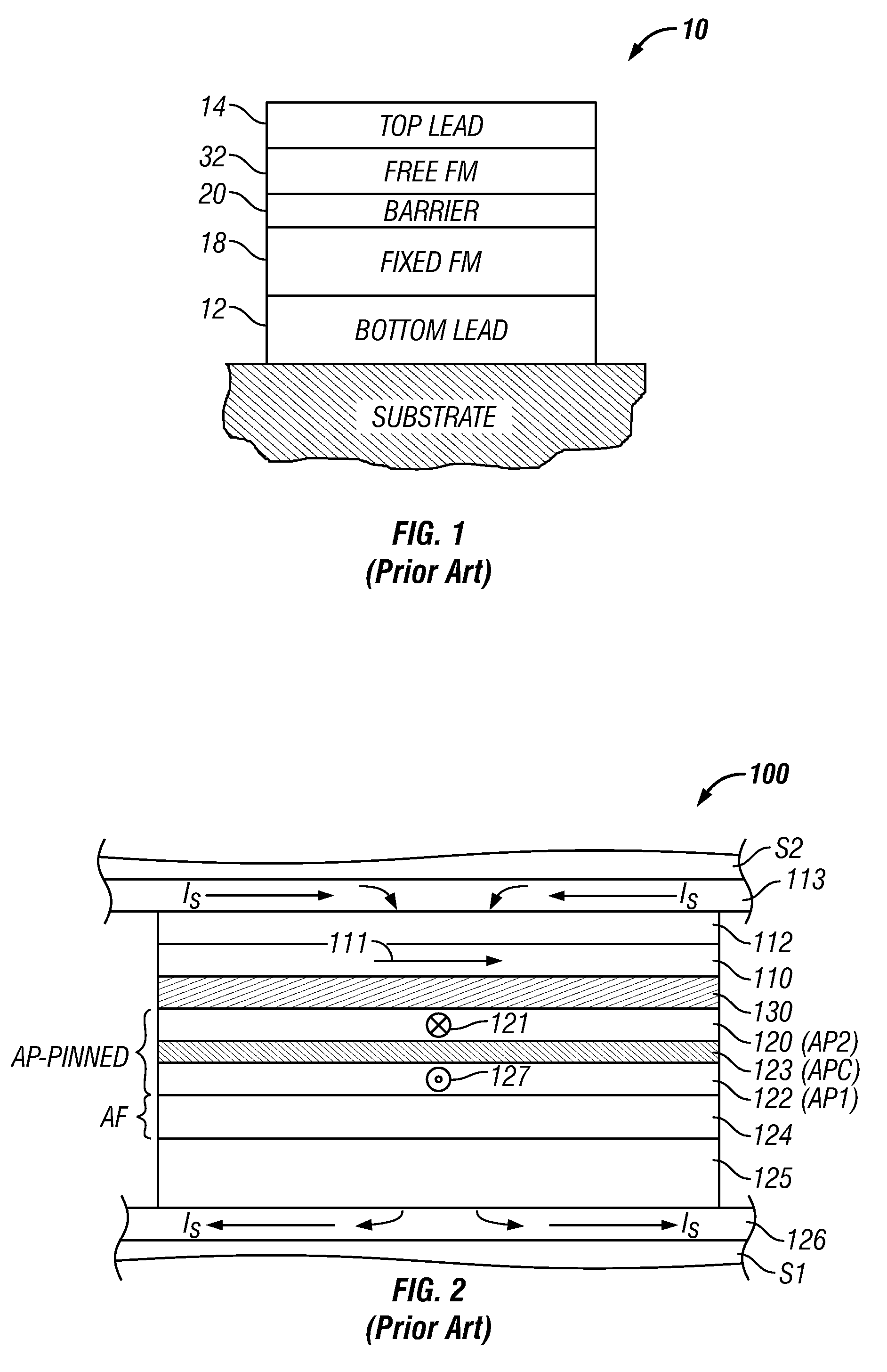
[0018]FIG. 2 is a cross-sectional view illustrating the structure of a prior-art TMR read head 100 like that used in a magnetic recording disk drive. This cross-sectional view is a view of what is commonly referred to as the air-bearing surface (ABS) of the TMR read head 100. The TMR read head 100 includes a sensor stack of layers formed between two ferromagnetic shield layers S1, S2 that are typically made of electroplated NiFe alloy films. The lower shield S1 is typically smoothened by chemical-mechanical polishing (CMP) to provide a smooth surface for the growth of the sensor stack. The sensor stack includes a ferromagnetic reference layer 120 having a pinned magnetization 121 oriented transversely (away from the page), a ferromagnetic free layer 110 having a magnetization 111 that can rotate in the plane of layer 110 in response to transverse external magnetic fields from a recording disk, and an electrically insulating barrier layer 130, typically made of an oxide, such as alum...


PUM

PropertyMeasurementUnit
pressureaaaaaaaaaa
thickaaaaaaaaaa
thickaaaaaaaaaa

Abstract

A method of forming a barrier layer of a tunneling magnetoresistive (TMR) device by forming first and second MgO barrier layers by different sputtering methods, but in the same sputtering system module. A first magnesium-oxide (MgO) barrier layer is formed over one of the TMR device's ferromagnetic layers by a DC magnetron sputter deposition from an Mg target in an oxygen environment. In the same module, a second MgO barrier layer is formed over the first MgO film by an RF sputter deposition from an MgO target and in an environment free of oxygen. Prior to the formation of the first MgO barrier layer, an optional Mg protection layer can be deposited on the ferromagnetic layer and oxidized by a first optional oxygen treatment. After deposition of the first MgO barrier layer, a second optional oxygen treatment may be conducted. After deposition of the second MgO barrier layer, a second Mg protection layer may be deposited by DC sputter deposition, followed by an optional third oxygen treatment.

Description

BACKGROUND OF THE INVENTION[0001]1. Field of the Invention[0002]The invention relates generally to tunneling magnetoresistive (TMR) devices, and more particularly to a method for forming a barrier layer consisting essentially of a magnesium oxide (MgO).[0003]2. Description of the Related Art[0004]A tunneling magnetoresistive (TMR) device, also called a magnetic tunneling junction (MTJ) device, is comprised of two ferromagnetic layers separated by a thin insulating tunneling barrier layer. The barrier layer is typically made of a metallic oxide, such as alumina (Al2O3) or MgO, that is so sufficiently thin that quantum-mechanical tunneling of charge carriers occurs between the two ferromagnetic layers. This quantum-mechanical tunneling process is electron spin dependent, which means that an electrical resistance measured when applying a sense current across the junction depends on the spin-dependent electronic properties of the ferromagnetic and barrier layers, and is a function of th...

Claims


Application Information

Patent Timeline
Patent Type & Authority Patents(United States)
IPC IPC(8): H01L21/00
CPCB82Y10/00B82Y25/00B82Y40/00G01R33/098G11B5/3163G11B5/3909G11C11/15H01F41/307H01L43/12G11B5/3906H01F10/3295H01F10/3254H10N50/01
Inventor LIN, TSANNMAURI, DANIELE
Owner WESTERN DIGITAL TECH INC
Why Eureka
Try Eureka