Sensing system with fiber gas sensor

a technology of fiber gas and sensing system, which is applied in the field of sensing system with an array of grating-based fiber gas sensors, can solve the problems of inability to direct online hsub>2 /sub>sensing technologies, conventional combustible gas sensors get saturated, and the difficulty of deploying such bulky and dedicated spectrometry-based sensors is obvious

Active Publication Date: 2009-02-10
GENERAL ELECTRIC CO
View PDF6 Cites 79 Cited by
  • Summary
  • Abstract
  • Description
  • Claims
  • Application Information

AI Technical Summary

Benefits of technology

[0006]In another aspect, a fiber gas sensor comprises a fiber core having a longitudinal axis; a long-period fiber grating structure having a first amplitude modulation profile positioned about the fiber core for sensing a localized gas concentration; a short-period fiber grating structure having a second amplitude modulation profile positioned about the fiber core at a distance along the longitudinal axis with respect to the long-period fiber grating structure for sensing a localized temperature; a fiber cladding positioned about the long-period and short-period fiber grating structures; and a sensing layer positioned about the fiber cladding of the long-period fiber grating structure, the sensing layer including a sensing material made of a group consisting of nano-PdOx, nano-Pd(x)Au(y)Ni(1-x-y) and nano-Pd / Au / WOx, wherein the gas sensor is capable of providing a temperature-corrected determination of the localized gas concentration.

Problems solved by technology

Existent H2 sensing technologies are largely unsuitable for direct online H2 concentration or composition monitoring due to several reasons.
One reason is that, because of high concentration of H2, such conventional combustible gas sensors get saturated.
At the same time, the difficulty of deploying such bulky and dedicated spectrometry based sensors is obvious, especially, in harsh environments of coal gasifier and Syngas or natural gas combustors for real-time online monitoring / analysis of fuel quality.
Although there are several conventional combustible gas sensors, such as infrared, electrochemical, metal oxide semiconductor based combustible gas-detection devices, they are either insensitive to hydrogen gas or saturated by high concentration or cannot be deployed in the harsh environments.

Method used


Image

  • Sensing system with fiber gas sensor
  • Sensing system with fiber gas sensor
  • Sensing system with fiber gas sensor

Examples


Embodiment Construction

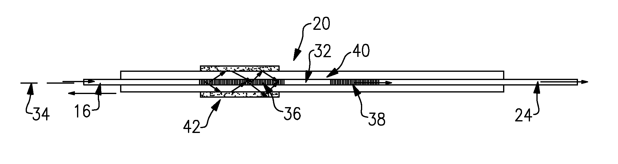
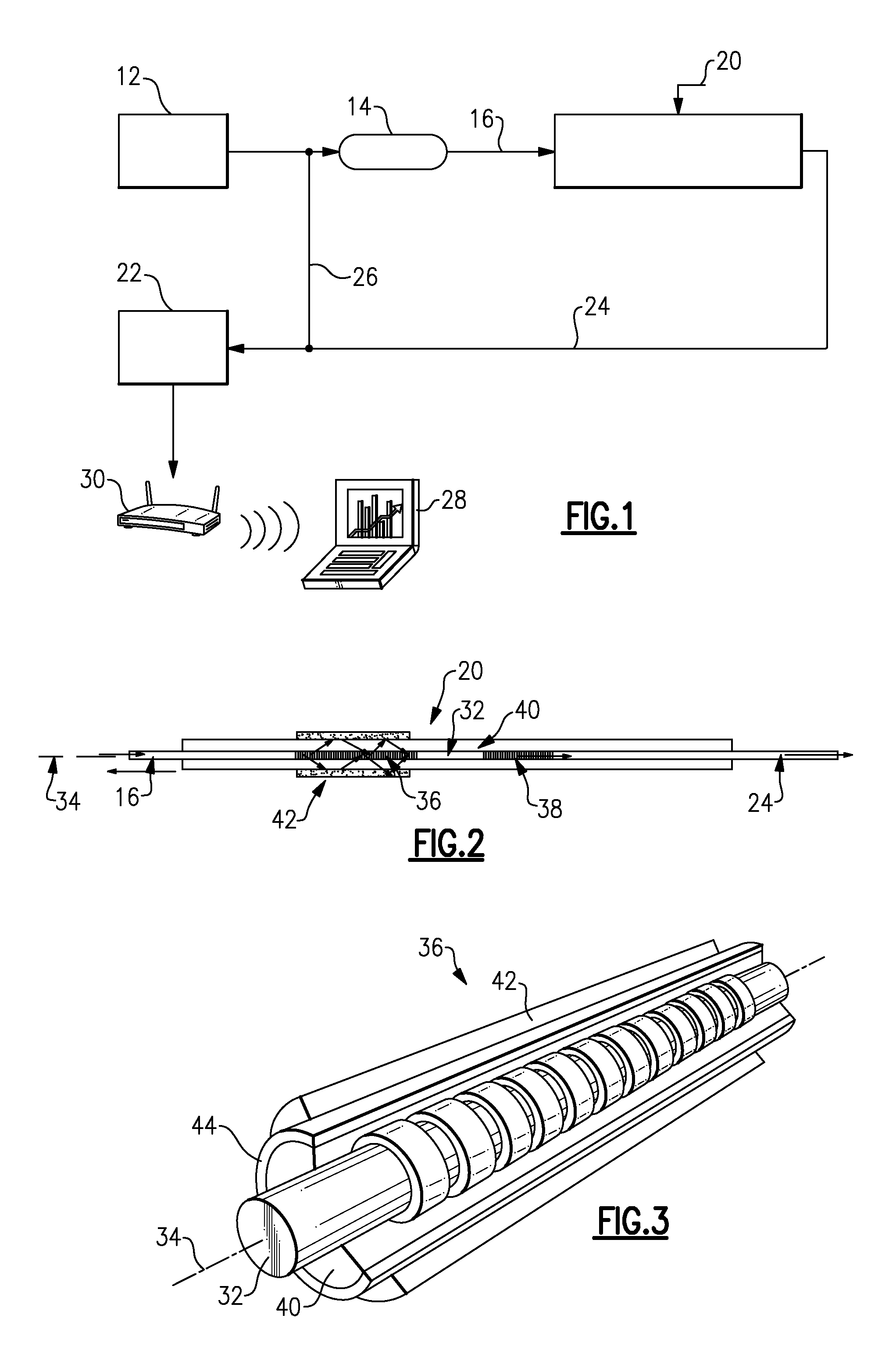
[0023]Referring now to FIG. 1, a sensing system 10 is schematically shown according to an embodiment of the invention. In general, the sensing system 10 includes a light source 12, such as tunable, broadband light source, in light communication with an optical coupler or circulator 14. The optical coupler 14 receives the light transmitted from the light source 12 and transmits a portion of the light through an optical fiber cable 16. The light passing through the optical fiber cable 16 enters one or more fiber gas sensors (FGS), shown generally at 20, according to the invention. A photodetector 22 positioned downstream of the fiber gas sensor 20 receives the transmitted light from the gas sensor 20 through an optical fiber cable 24. A portion of the light reflected by the optical coupler 14 is also received by the photodetector 22 through an optical fiber cable 26. The light signal generated by fiber gas sensor(s) 20 is processed and / or transmitted to a computer 28. In an embodiment...


PUM


Abstract

A fiber gas sensor includes a fiber core with first and second refractive index periodic modulated grating structures having different amplitude modulation profiles positioned about the fiber core. A fiber cladding is positioned about the first and second refractive index periodic modulated grating structures. A sensing layer is positioned about the fiber cladding of one of the refractive index periodic modulated grating structures. The sensing layer includes a sensing material made of a Pd-based alloy, such as nano-PdOx, nano-Pd(x)Au(y)Ni(1-x-y) or nano-Pd/Au/WOx. The fiber gas sensor provides a measurement of localized, temperature-corrected gas concentration and composition from a combustion environment. A reflection-based or a transmission-based sensing system with an array of one or more fiber gas sensors is also described.

Description

BACKGROUND OF THE INVENTION[0001]This invention relates generally to sensing systems and sensors, and, more particularly, to a sensing system with an array of grating-based fiber gas sensors that provide a measurement of a temperature-corrected gas concentration.[0002]Power generating systems are being built today that have turbines using Syngas (hydrogen (H2) mixing with carbon monoxide (CO)) as fuel. The Syngas can be generated using a coal gasifier or other industrial processes. Also, gas turbines today can use a blend of Natural Gas (NG) and H2 fuel for power generation in order to obtain better operability, efficiency or emissions control. Typically, fuel streams used by turbines could contain Natural Gas (NG), which is primarily methane (CH4), diluents such as nitrogen (N2) and Carbon Monoxide (CO) and Carbon Dioxide (CO2), as well as higher molecular weight hydrocarbons, such as ethane (C2H6) and propane (C3H8). A hydrogen containing fuel could be a blend of low percentage of...

Claims


Application Information

Patent Timeline
Patent Type & Authority Patents(United States)
IPC IPC(8): G02B6/00G01K11/3206
CPCG01N21/774G02B6/02095G02B6/02104F23N2021/10F23N2041/20G01N2021/7709G01N2021/7776F23N2221/10F23N2241/20
Inventor XIA, HUAGOLDMEER, JEFFREY SCOTTMCCARTHY, KEVIN THOMASKUMAR, ADITYAANNIGERI, RAVINDRAYILMAZ, ERTANTAWARE, AVINASH VINAYAKZHAO, YU
Owner GENERAL ELECTRIC CO
Why Eureka
Try Eureka