
Thin film etching method and method of fabricating liquid crystal display device using the same

a thin film etching and liquid crystal display technology, applied in semiconductor devices, instruments, electrical devices, etc., can solve the problems of unfavorable product quality control, and difficulty in managing temperature, concentration, etc., to improve process productivity and simplify the process

Active Publication Date: 2009-02-17
LG DISPLAY CO LTD
View PDF7 Cites 9 Cited by
  • Summary
  • Abstract
  • Description
  • Claims
  • Application Information

AI Technical Summary

Benefits of technology

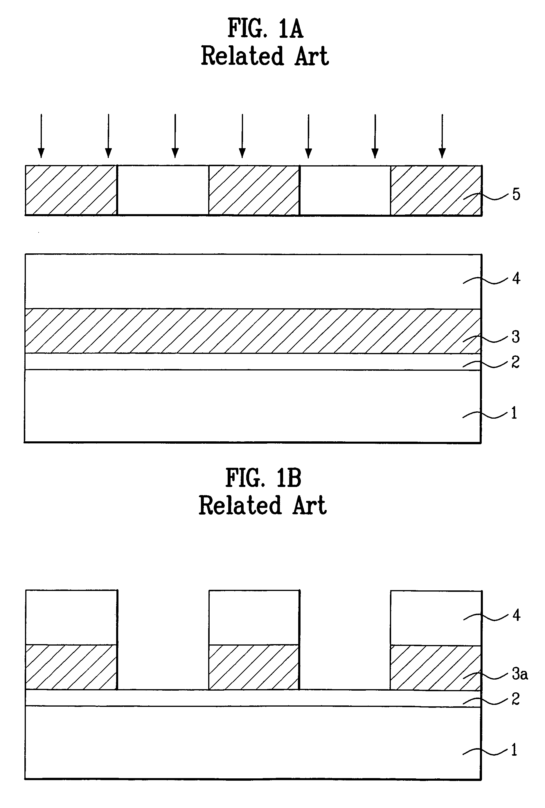
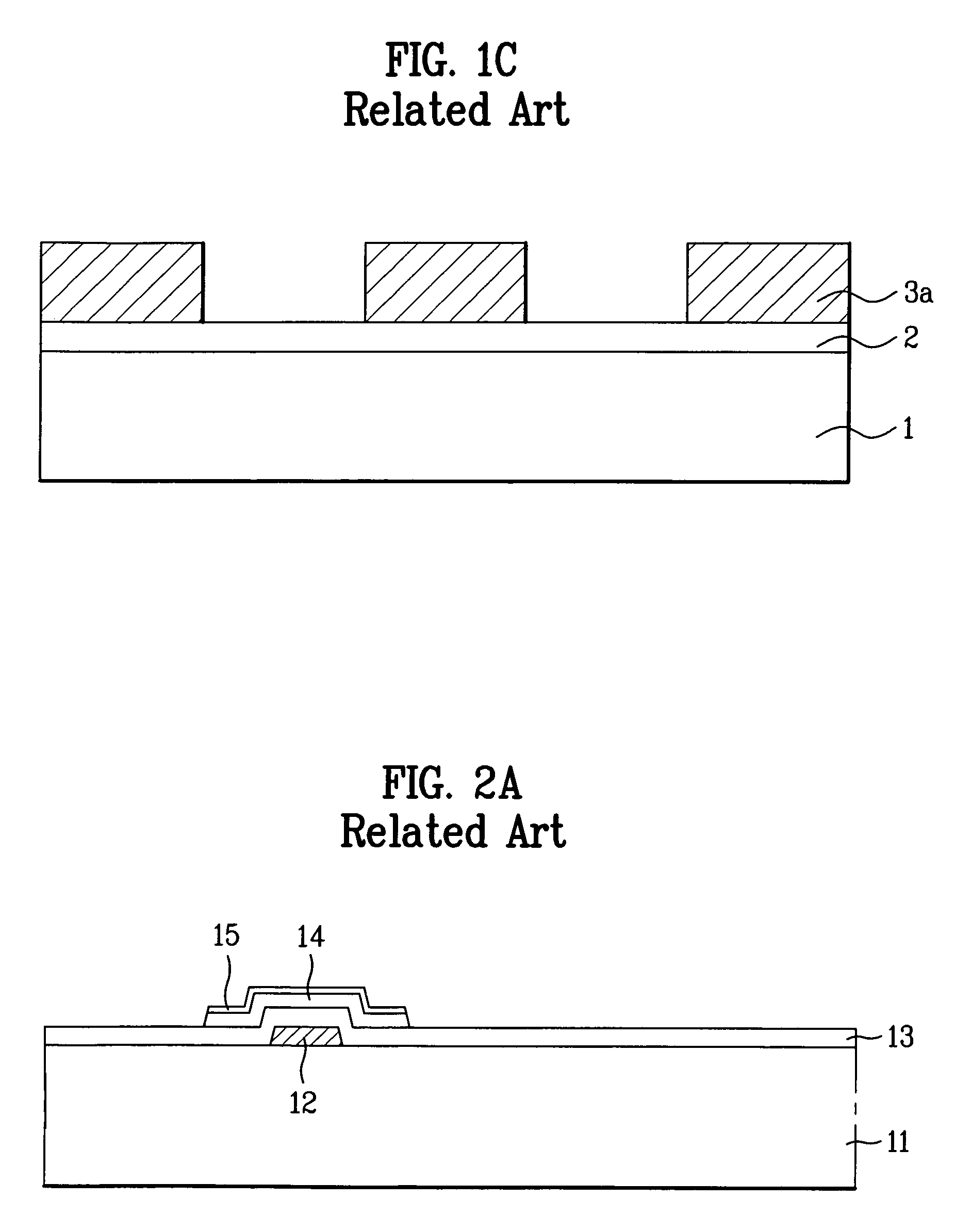
The present invention provides a thin film etching method and a method of fabricating a liquid crystal display device using the same that overcome the limitations and disadvantages of related art. The method includes using a femtosecond laser to remove a portion of a layer on a substrate, which simplifies the process and improves productivity. The method also includes forming a layer on a substrate, aligning a mask with a pattern, and removing a portion of the layer using the femtosecond laser to create a patterned layer. The method further includes forming additional layers, removing portions of them using the femtosecond laser, and creating contact holes and pixel electrodes to connect the layers and create a display. The technical effects of the invention include simplifying the process, improving productivity, and creating more precise and reliable patterns.

Problems solved by technology

In the deposition development method, it is difficult to manage temperature, concentration, aging effect and the like.
However, such a method needs expensive equipment to generate the O2 plasma, and rotational particles in the O2 plasma cause undesired damage to a substrate.
Thus, the fabrication process is time consuming and expensive.
However, it is difficult for using the screen mask with a large-sized substrate.
In addition, the screen print method induces failure due to the contact between the mask and the alignment layer.
When the liquid crystal molecules are injected in the LCD panel, air amongst the liquid crystal molecules creates bubbles within the LCD panel that cause device failure.
Accordingly, the related art method repeats the above steps, thereby complicating the fabrication process and lowering productivity.

Method used


Image

  • Thin film etching method and method of fabricating liquid crystal display device using the same
  • Thin film etching method and method of fabricating liquid crystal display device using the same
  • Thin film etching method and method of fabricating liquid crystal display device using the same

Examples


Embodiment Construction

[0038]Reference will now be made in detail to the preferred embodiments of the present invention, examples of which are illustrated in the accompanying drawings.

[0039]A laser ablation is used in fabricating a high precision and purity part. When using a fast pulse, ablation is advantageous that it causes less thermal damage to the surroundings. For example, a nanosecond laser processing machine is a laser processing machine using an YAG laser or an excimer laser of 10−9 m / s pulse unit. When the processing machine using an YAG laser, which generates a laser by artificial crystalline particles of aluminum oxide, a processed sidewall becomes coarse. When the processing machine using an IR CO2 laser, a crater is formed at the processed portion. Thus, it is difficult to provide a fine processing requiring a precision below micrometer unit, because in such a laser heat processing, photo energy is converted to thermal energy. As a result, the corresponding processed shape is easily breakab...


PUM

PropertyMeasurementUnit
conductiveaaaaaaaaaa
non-transparentaaaaaaaaaa
photosensitiveaaaaaaaaaa

Abstract

A thin film etching method includes forming a layer on a substrate, aligning a mask having a pattern defined thereon above the layer, and removing a portion of the layer by irradiating the substrate with a femtosecond laser through the mask.

Description

[0001]The present invention claims the benefit of Korean Patent Application No. P2004-0089705 filed in Korea on Nov. 5, 2004, which is hereby incorporated by reference.BACKGROUND OF THE INVENTION[0002]1. Field of the Invention[0003]The present invention relates to a liquid crystal display device and, more particularly, a thin film etching method and a method of fabricating a liquid crystal display device using the same. Although the present invention is suitable for a wide scope of applications, it is particularly suitable for process simplification and manufacturing cost reduction of thin films.[0004]2. Discussion of the Related Art[0005]As the information-oriented society is developing, the demands for display devices gradually rise. Many efforts have been made to research and develop various flat panel display devices, such as liquid crystal display (LCD) devices, plasma display panel (PDP) devices, electroluminescent display (ELD) devices and vacuum fluorescent display (VFD). Am...

Claims


Application Information

Patent Timeline
Patent Type & Authority Patents(United States)
IPC IPC(8): H01L21/00
CPCH01L27/124G02F1/136
Inventor PARK, JEONG KWEON
Owner LG DISPLAY CO LTD
Learn More