
Epitaxial deposition process and apparatus

a technology of epitaxial deposition and deposition process, applied in the direction of crystal growth process, polycrystalline material growth, chemically reactive gas, etc., can solve the problems of high temperature process in thermal budgeting, detrimental impact of epitaxial growth process, and error in subsequent atomic ordering

Inactive Publication Date: 2009-02-24
APPLIED MATERIALS INC
View PDF16 Cites 242 Cited by
  • Summary
  • Abstract
  • Description
  • Claims
  • Application Information

AI Technical Summary

Benefits of technology

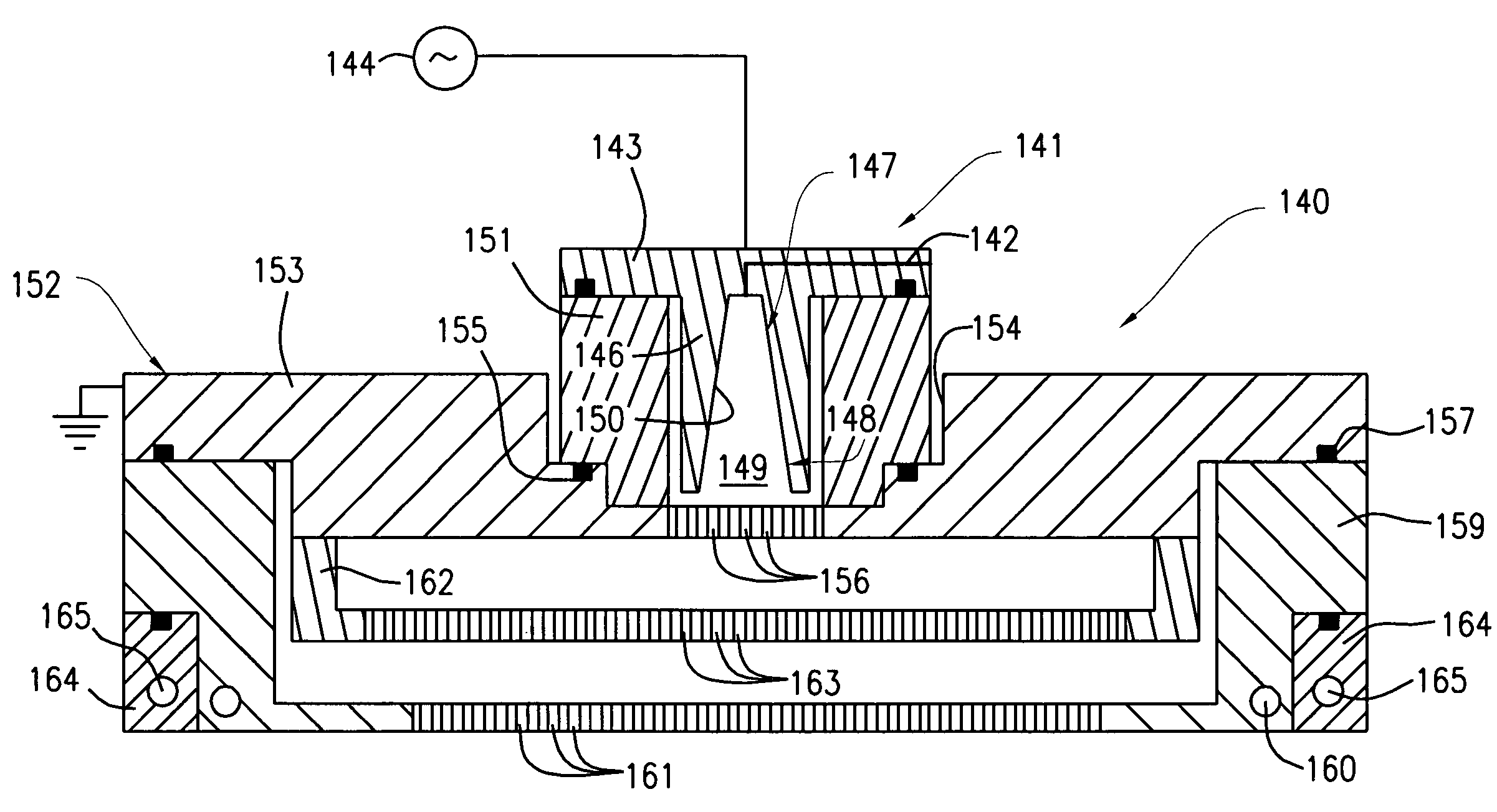
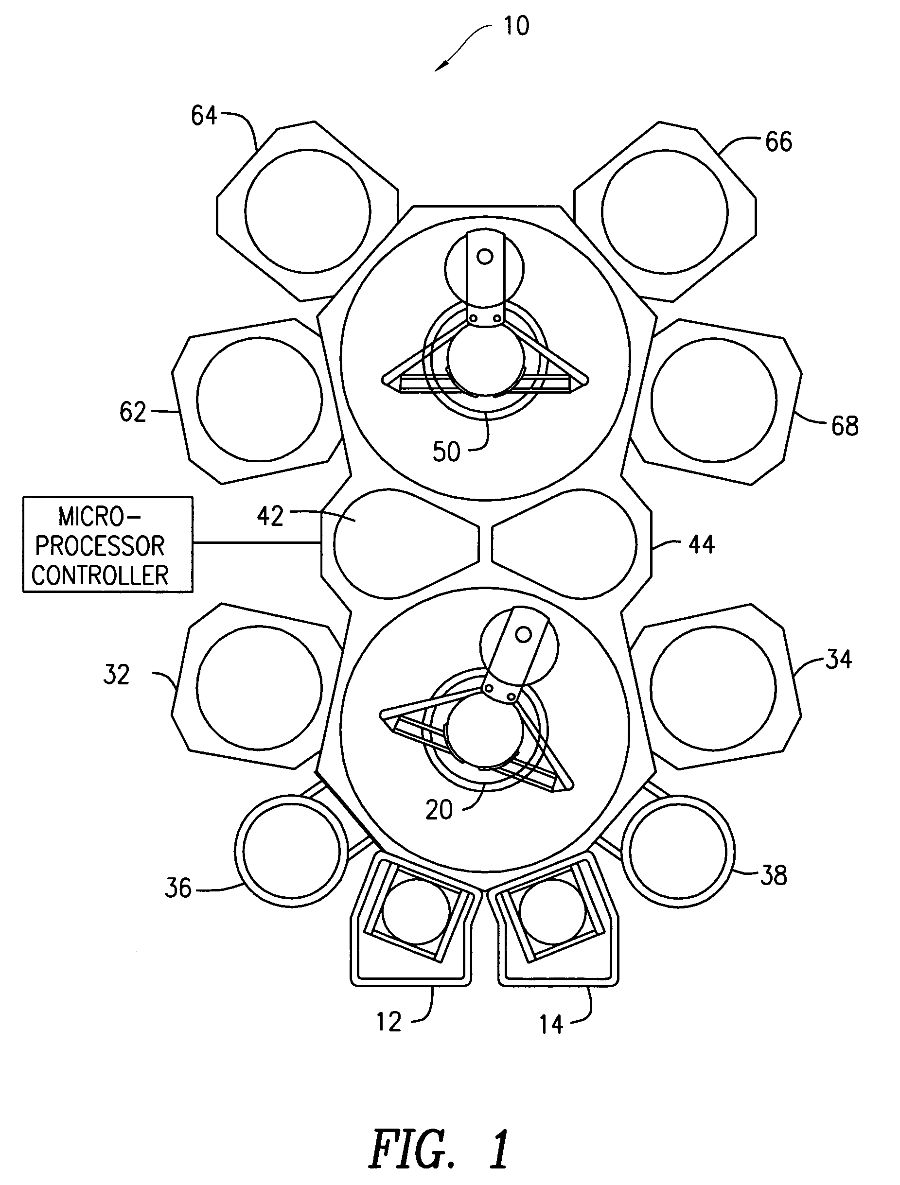
The present invention is about a processing apparatus that can remove oxide from a substrate surface and form an epitaxial layer on it without exposing it to ambient air. The apparatus includes a dry etch processor and an epitaxial deposition reactor connected in a vacuum-tight connection. The substrate is first cleaned in the dry etch processor to remove oxide and expose an epitaxy surface, and then transferred to the epitaxial deposition reactor without exposure to ambient air. The epitaxial layer is formed on the epitaxy surface. The technical effect of this invention is to provide a more efficient and effective method for cleaning and epitaxial layer formation on substrates.

Problems solved by technology

If the surface oxygen content of the substrate is too high, the epitaxial growth process will be detrimentally affected, as the oxygen atoms interfere with the crystallographic placement of the depositing material on the seed substrate.
This local atomic displacement can create an error in the subsequent atomic ordering as the layer is grown thicker.
However, such high temperature processes are expensive in terms of thermal budgeting.
Although the HF-last pre-clean step is effective in the removal of native oxide from the substrate surface, it introduces a certain amount of complexity into the manufacturing process.
First, because it is a wet process, HF-last imposes an inherent queue time between the wet-clean station and the epitaxy deposition reactor.
Secondly, the isotropic etching of the diluted HF solution used in the HF-last pre-clean step may undercut oxide.
Finally, selectivity issues arise with the oxide-nitride-silicon etch rates in the HF solution for silicon substrates.

Method used


Image

  • Epitaxial deposition process and apparatus
  • Epitaxial deposition process and apparatus
  • Epitaxial deposition process and apparatus

Examples


Embodiment Construction

[0014]Before describing several exemplary embodiments of the invention, it is to be understood that the invention is not limited to the details of construction or process steps set forth in the following description. The invention is capable of other embodiments and of being practiced or being carried out in various ways.

[0015]Aspects of the invention relate to systems, apparatus and methods for epitaxial deposition of films onto substrates. As will be appreciated by the skilled artisan, well-known semiconductor processing equipment and techniques relating to epitaxial deposition are not described in detail in the following so as to not unnecessarily obscure the present invention. Persons skilled in the art will readily recognize that process parameter values will vary significantly depending on the particular environment, substrate type, etc. As such, a comprehensive list of possible values and conditions is neither practical nor necessary, as such values can be determined once the...


PUM

PropertyMeasurementUnit
temperatureaaaaaaaaaa

Abstract

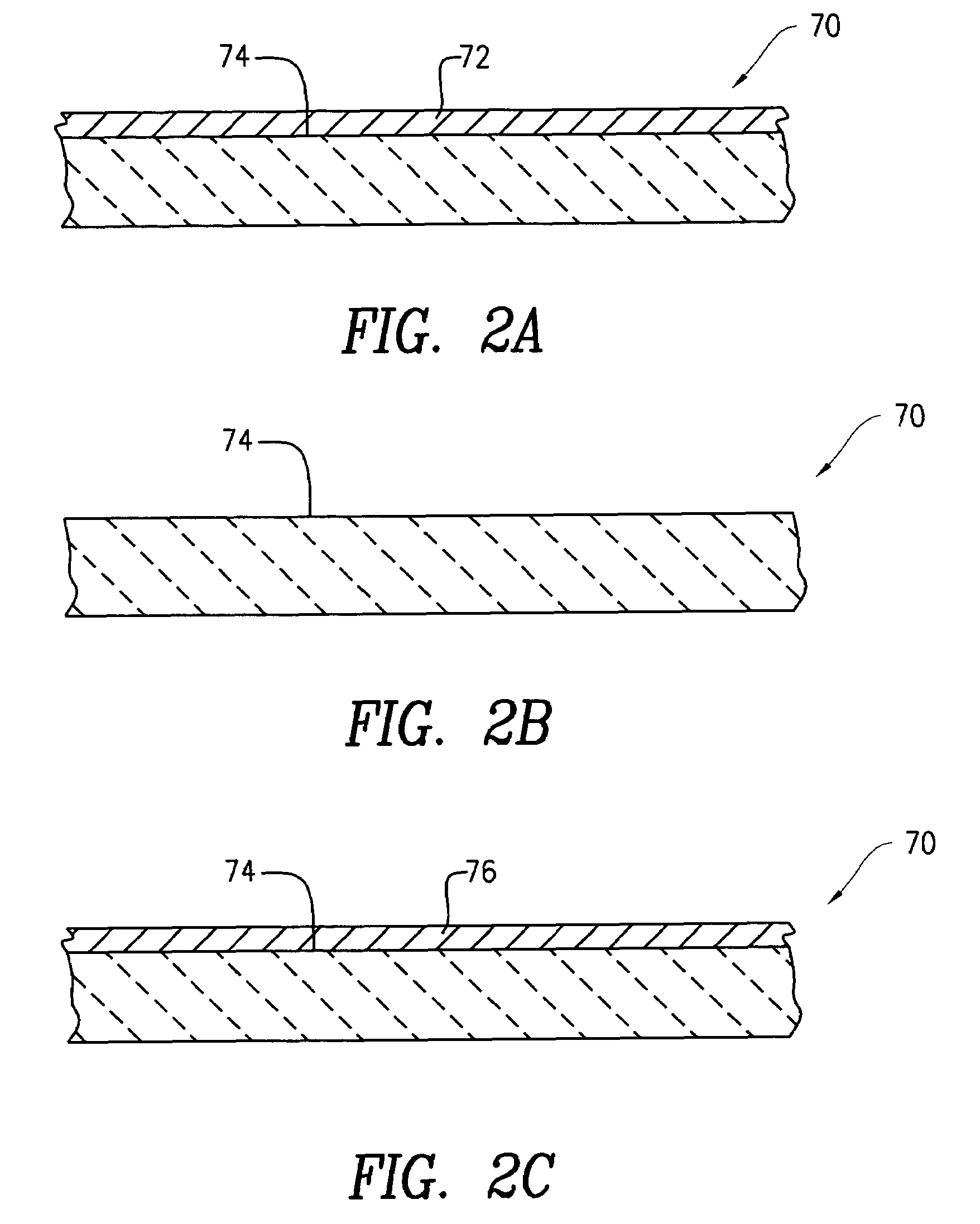
An epitaxial deposition process including a dry etch process, followed by an epitaxial deposition process is disclosed. The dry etch process involves placing a substrate to be cleaned into a processing chamber to remove surface oxides. A gas mixture is introduced into a plasma cavity, and the gas mixture is energized to form a plasma of reactive gas in the plasma cavity. The reactive gas enters into the processing chamber and reacts with the substrate, forming a thin film. The substrate is heated to vaporize the thin film and expose an epitaxy surface. The epitaxy surface is substantially free of oxides. Epitaxial deposition is then used to form an epitaxial layer on the epitaxy surface.

Description

TECHNICAL FIELD[0001]Embodiments of the present invention pertain to epitaxial deposition methods, systems and apparatus. In particular, epitaxial deposition methods, systems and apparatus that involve a cleaning process used to remove surface oxide prior to the epitaxy process are disclosed.[0002]An epitaxial layer is a crystalline film grown over a crystalline substrate. The underlying substrate acts as a template for the growing film, so that the crystallographic characteristics of the epitaxial layer are defined by the underlying crystalline substrate. That is, the crystalline substrate provides a crystallographic seed for the epitaxial growth. The substrate may be, for example, monocrystalline silicon, silicon germanium or an SOI wafer.[0003]Growth of the epitaxial layer is commonly achieved using chemical vapor deposition (CVD). The substrate wafer is loaded into a CVD reactor, which is then purged with a non-reactive gas such as He, Ar, N2, or H2. The temperature of the react...

Claims


Application Information

Patent Timeline
Patent Type & Authority Patents(United States)
IPC IPC(8): C30B25/12
CPCC23C16/0236C23C16/452C23C16/505H01L21/31116H01L21/67069H01L21/20
Inventor LAM, ANDREWKIM, YIHWANKUPPURAO, SATHEESHPHAN, SEE-ENGLU, XINLIANGKAO, CHIEN-TEH
Owner APPLIED MATERIALS INC
Learn More