In-situ power monitor providing an extended range for monitoring input optical power incident on avalanche photodiodes

a technology of optical power incident and power monitor, which is applied in the direction of optical radiation measurement, photometry using electric radiation detector, instruments, etc., can solve the problems of degrading optical power monitoring, inability to adjust the gain of the in-line apd during normal operation of the apd, and prone to noise and temperature variations, so as to reduce leakage currents and achieve effective immunity

Active Publication Date: 2009-02-24
ALLIED TELESIS
View PDF7 Cites 12 Cited by
  • Summary
  • Abstract
  • Description
  • Claims
  • Application Information

AI Technical Summary

Benefits of technology

[0008]Disclosed are an in-line monitoring apparatus, an optical receiver and a method for monitoring an input power of an optical signal over an extended range in which one or more power monitoring stages, for example can measure the input power over an extended input power range. In one embodiment, an in-line monitoring apparatus includes an avalanche photodiode (“APD”) configured to receive the optical signal and an input configured to provide a bias for the APD. It also includes one or more power monitoring stages coupled to the input in parallel with the APD for generating one or more measurement signals in-situ. The measurement signals are representative of an input optical power. In one embodiment, a range selector selects which one of the one or more power monitoring stages is to provide a measurement signal indicative of the input optical power. Generally, the one or more power monitoring stages have high-impedance inputs for reducing leakage currents. At least one of the power monitoring stages can be configured to provide a range of measurable current to monitor low-powered optical signals with effective immunity to noise at those levels, such as at −45 dBm or lower. The in-line monitoring apparatus obviates the need for external power monitors and series power monitoring devices, such as logarithmic amplifiers and current mirror in series with the APD. The in-line monitoring apparatus also provides for both real-time gain calibration and alarm limit evaluation over the same extended range of input optical power. In some embodiments, the power monitoring stages can provide for a wide range of linear current measurements while also providing a range of measurable currents to monitor low-powered optical signals.

Problems solved by technology

The operation of the APD, however, is susceptible to noise and variations in temperature.
But conventional structures and techniques for facilitating photocurrent measurements and bias voltage adjustments have several drawbacks.
As such, in-line APD gain adjustments are generally not feasible during normal operations of the APD, especially when it is being used in a communications network.
Another drawback to configuration 100 is that external power monitor 120 introduces an additional component causing signal losses in the optical path, thereby degrading optical power monitoring.
But there are several drawbacks to this approach to monitoring input optical power.
One drawback is that precise signal splitting is technically difficult without disturbing the high-frequency nature of main output signal 208.
But with main output signal 208 commonly being at high frequencies and data transfer rates, such as at 10 Gbps or higher, it is difficult to effectively split the signal for accurate power monitoring. FIG. 2B shows that another drawback to structure 200 in monitoring power is that it has a relatively high-degree of non-linearity, which significantly reduces the total range over which to monitor optical power.

Method used


Image

  • In-situ power monitor providing an extended range for monitoring input optical power incident on avalanche photodiodes
  • In-situ power monitor providing an extended range for monitoring input optical power incident on avalanche photodiodes
  • In-situ power monitor providing an extended range for monitoring input optical power incident on avalanche photodiodes

Examples


Embodiment Construction

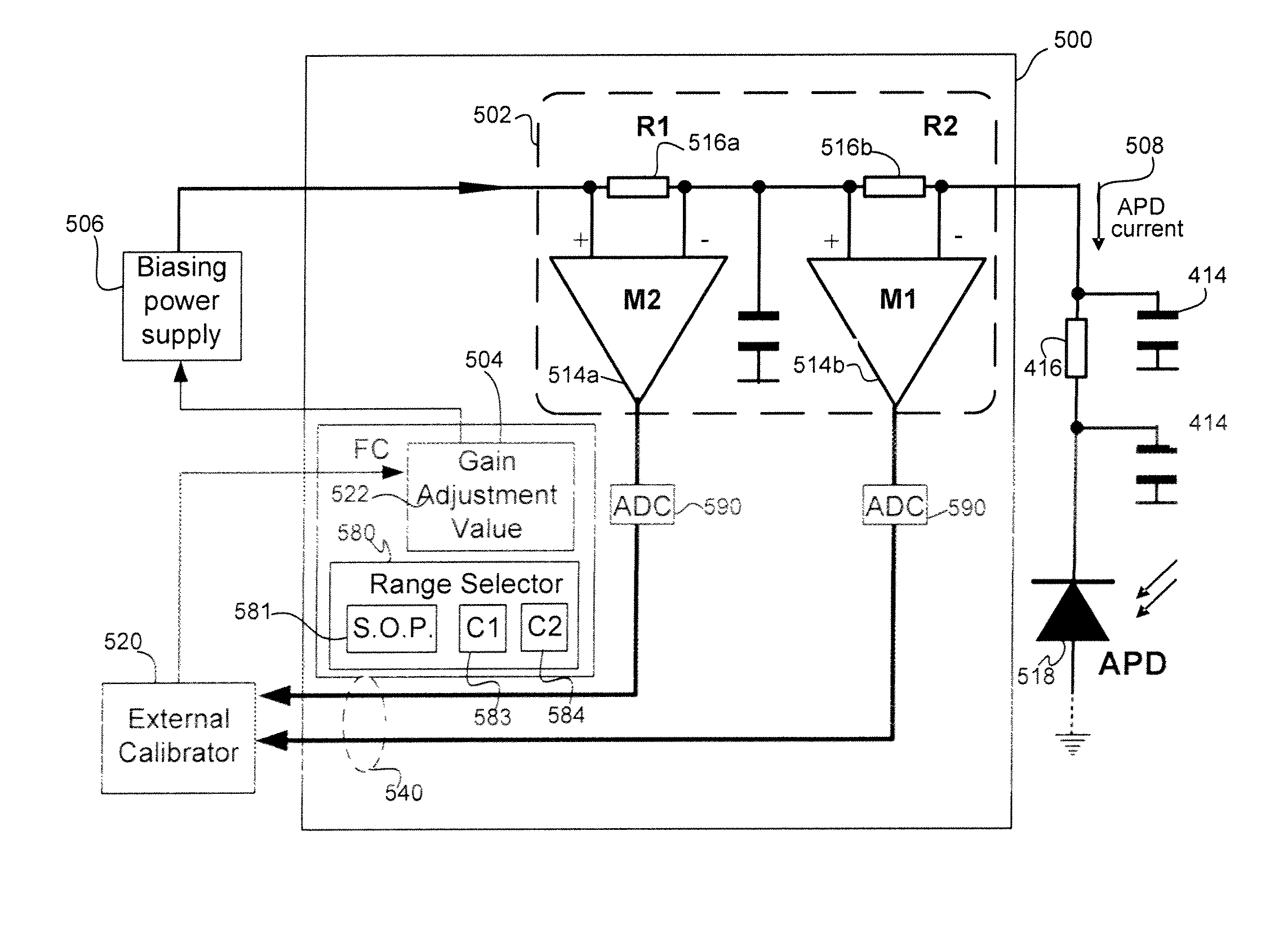
[0026]FIG. 4 is a block diagram of an apparatus that monitors input optical power in-line, according to at least one specific embodiment of the invention. Apparatus 400 includes an in-line power monitor 402 configured to monitor an optical signal 420 into an optical signal detector by, for example, sensing a current 408 flowing from a biasing source (“biasing power supply”) 406, which can provide an adjustable bias voltage. In one embodiment, the optical signal detector is an APD 418. In some cases, a resistance 416 and / or capacitors 414 filter current 408 to reduce, for example, the effects of noise. Apparatus 400 also includes a passive element 403, which can replace 416, to detect and to monitor current 408.

[0027]Note that a current 408 through the APD can be described in accordance with Equation (1) as follows:

I(APD_current)=Ip*APD(responsitivity)*APD(gain),  Equation (1)

where Ip represents the photon flux into APD 418, APD(responsitivity) represents the responsitivity of APD 41...


PUM


Abstract

Disclosed are an in-line monitoring apparatus, an optical receiver and a method for monitoring an input power of an optical signal in which one or more power monitoring stages, for example can measure the input power over an extended input power range. In one embodiment, an apparatus includes an avalanche photodiode (“APD”) configured to receive the optical signal and an input configured to bias the APD. It also includes one or more power monitoring stages coupled to the input in parallel with the APD for generating one or more measurement signals in-situ. In one embodiment, a range selector selects which one of the one or more power monitoring stages is to provide a measurement signal indicative of the input optical power. The power monitoring stages can provide for a wide range of linear current measurements as well as a range of measurable currents to monitor low-powered optical signals.

Description

BRIEF DESCRIPTION OF THE INVENTION[0001]This invention relates generally to an in-line power monitor, and more particularly, to an in-line power monitor for monitoring input power of an optical signal detector, such as an avalanche photodiode (“APD”). By monitoring the input power in-line, operational parameters of the optical signal detector can be determined and controlled in real-time. For example, the gain of an APD as an operational parameter can be controlled as its temperature varies.BACKGROUND OF THE INVENTION[0002]Optical receivers facilitate data transfer by detecting optical signals transmitted over optical fiber cables in optical communications networks. In such networks, an optical transmitter modulates optical signals at high frequencies to send them over a fiber using one or more optical wavelengths. To receive the transmitted signals, optical receivers typically use avalanche photodiodes (“APDs”) to detect the optical signals. As is known, an APD is a photodiode that...

Claims


Application Information

Patent Timeline
Patent Type & Authority Patents(United States)
IPC IPC(8): H03F3/08
CPCH04B10/0799H04B10/672H04B10/07H04B10/60H01L31/10
Inventor KAKU, SHINKYOTIKHONOV, VITALI
Owner ALLIED TELESIS
Why Eureka
Try Eureka