Structure and method of chemically formed anchored metallic vias
a technology of chemical formation and metallic vias, which is applied in the direction of semiconductor devices, semiconductor/solid-state device details, electrical apparatus, etc., can solve the problems of increasing the number of integrated circuits, new integration challenges, and reducing the efficiency of routing these signals across the device, so as to achieve elimination or significant reduction of the sputter-etching process, the effect of high stress migration
- Summary
- Abstract
- Description
- Claims
- Application Information
AI Technical Summary
Benefits of technology
Problems solved by technology
Method used
Image
Examples
first embodiment
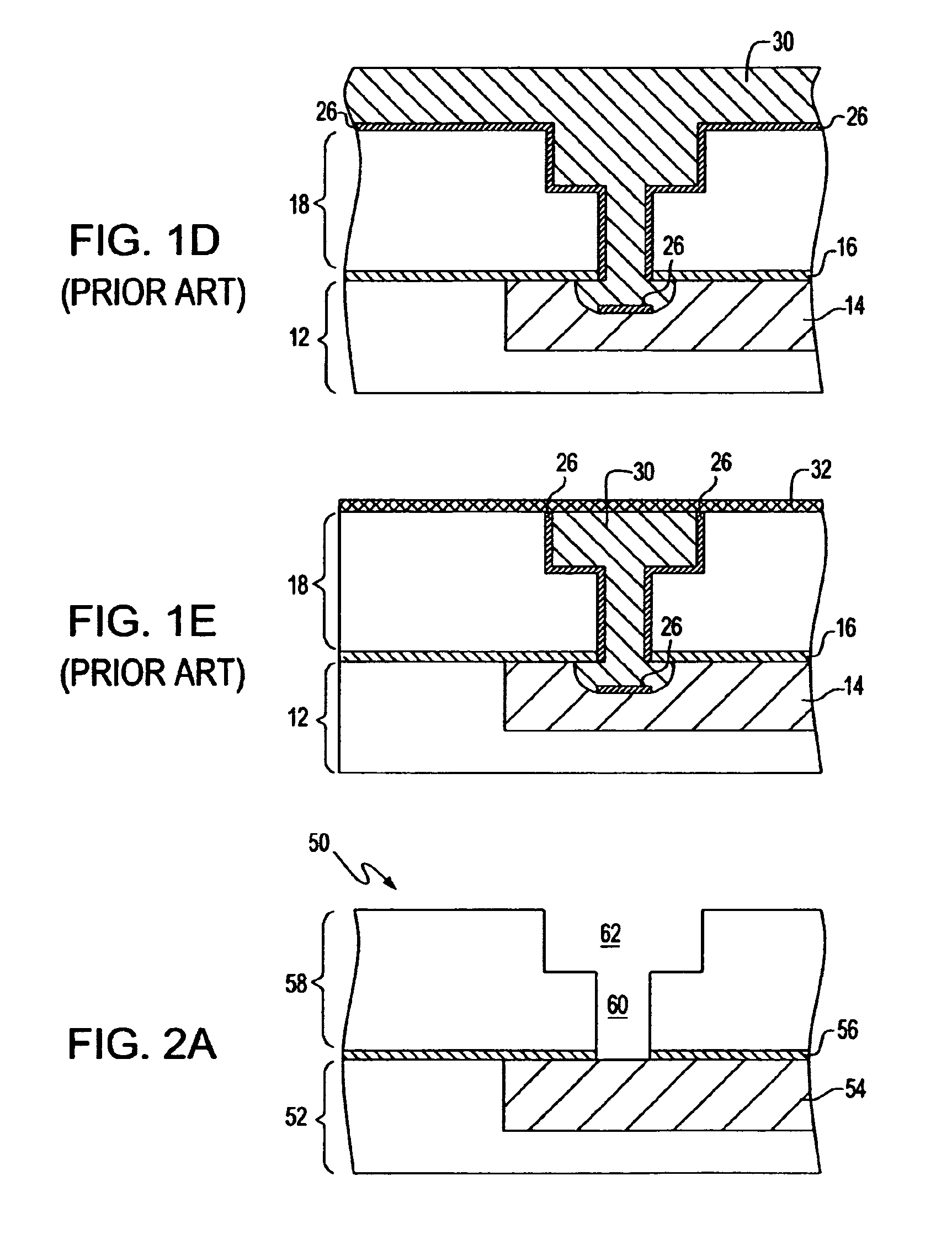
[0060]the present invention is now described in greater detail by referring to FIGS. 2A-2E. FIG. 2A shows an initial structure 50 prior to construction of the anchoring recessed area that includes a lower interlevel dielectric (ILD) 52 having at least one metal line 54 embedded therein. The metal line 54 is typically separated from the ILD 52 by a diffusion barrier (not shown). The initial structure also includes a first dielectric cap 56 having an opening that exposes a surface of the at least one metal line 54 atop the lower ILD 52. An upper ILD 58 having at least one via opening 60 and, optionally, at least one line opening 62 is located on the first dielectric cap 56. As illustrated, the at least one via opening 60 is located beneath the at least one line opening 62 and the at least one via opening 60 is substantially aligned with the opening provided in the first dielectric cap 56.
[0061]The processing of the initial structure 50 shown in FIG. 2A includes any conventional dual d...
second embodiment
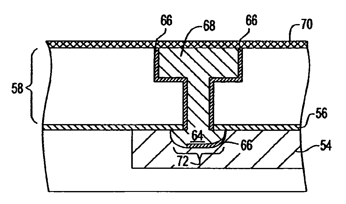
[0093]In an analogous manner to the construction illustrated in FIGS. 2A-2E and alternate structure can be produced. In this second embodiment, the structure is built in the same manner as the embodiment described above up until the formation of the structure shown in FIG. 2C, the analog structure shown in FIG. 3A is a line of sight deposition structure.
[0094]After producing the structure shown in FIG. 3A, a method to redistribute part of the liner and / or seed is employed to spread the liner and / or seed beyond the line of sight aperture, then a conductive material 68 such as, for example, a conductive metal or metal alloy, is deposited within the anchoring recessed area 64, the via opening 60 and the line opening 62 as well as atop the liner 66 that lies on the horizontal surface of the upper ILD 58. Examples of conductive material 68 that can be used in the present invention include, but are not limited to: W, Al, Cu, Ag, Al—Cu and other like conductive materials. Preferably, the c...
third embodiment
[0095]FIG. 4 shows another semiconductor Interconnect structure (e.g., third embodiment) that can be formed wherein the liner 66 is continuously present on the exposed surface of the etched metal line 54 within the anchoring recessed area 64, on the underside of the first dielectric cap 56 in the undercut provided during etching of the metal line 54, and on the exposed sidewalls of the upper ILD 58. In this embodiment of the present invention, the continuous liner 66 is formed by ALD or controlled resputtering during PVD deposition. All the other processing steps as described above are the same in forming the alternative structure shown in FIG. 4.
[0096]Reference will now be made to FIGS. 5A-5I which illustrate a fourth embodiment of the present invention. In the fourth embodiment of the present invention, a targeted oxidation process which enables a subsequent chemical etch process to selectively remove oxidized ILD and metal materials is employed. The resultant structure provides f...
PUM
| Property | Measurement | Unit |
|---|---|---|
| dielectric constant | aaaaa | aaaaa |
| resistance | aaaaa | aaaaa |
| resistance | aaaaa | aaaaa |
Abstract
Description
Claims
Application Information
 - R&D
- Intellectual Property
- Life Sciences
- Materials
- Tech Scout
- Unparalleled Data Quality
- Higher Quality Content
- 60% Fewer Hallucinations
Browse by: Latest US Patents, China's latest patents, Technical Efficacy Thesaurus, Application Domain, Technology Topic, Popular Technical Reports.
© 2025 PatSnap. All rights reserved.Legal|Privacy policy|Modern Slavery Act Transparency Statement|Sitemap|About US| Contact US: help@patsnap.com


