Low eddy current vacuum vessel and method of making same

a vacuum vessel and low eddy current technology, applied in the field of magnetic resonance imaging (mri), can solve the problems of generating eddy current and unwanted field distortion in the imaging volume, adversely affecting image quality, structural or thermal problems, etc., and achieve the effect of reducing the formation of eddy currents

Active Publication Date: 2009-04-14
GENERAL ELECTRIC CO
View PDF7 Cites 11 Cited by
  • Summary
  • Abstract
  • Description
  • Claims
  • Application Information

AI Technical Summary

Benefits of technology

[0007]The present invention overcomes the aforementioned drawbacks by providing an apparatus, and a method of manufacturing thereof, for reducing the formation of eddy currents in a vacuum vessel and for ensuring that the vacuum vessel is free of leaks to provide a reliable pressure boundary.

Problems solved by technology

Although, metal vacuum vessels are strong enough to resist vacuum forces, they generate eddy currents and unwanted field distortions in the imaging volume when exposed to an AC field, such as an AC field generated by gradient coils of the MR system.
The eddy currents in the vacuum vessel of a MRI system generate un-wanted field distortions in the imaging volume and adversely affect the image quality.
The eddy current heating may also cause structural or thermal problems.
That is, the AC losses add to the total heat load and increase costs for maintain the helium at a cryogenic temperature.
Any leakage and gas permeation into and out of the vacuum vessel will, over time, increase the vacuum pressure and thus increase the heat load of the magnet.

Method used


Image

  • Low eddy current vacuum vessel and method of making same
  • Low eddy current vacuum vessel and method of making same
  • Low eddy current vacuum vessel and method of making same

Examples


Embodiment Construction

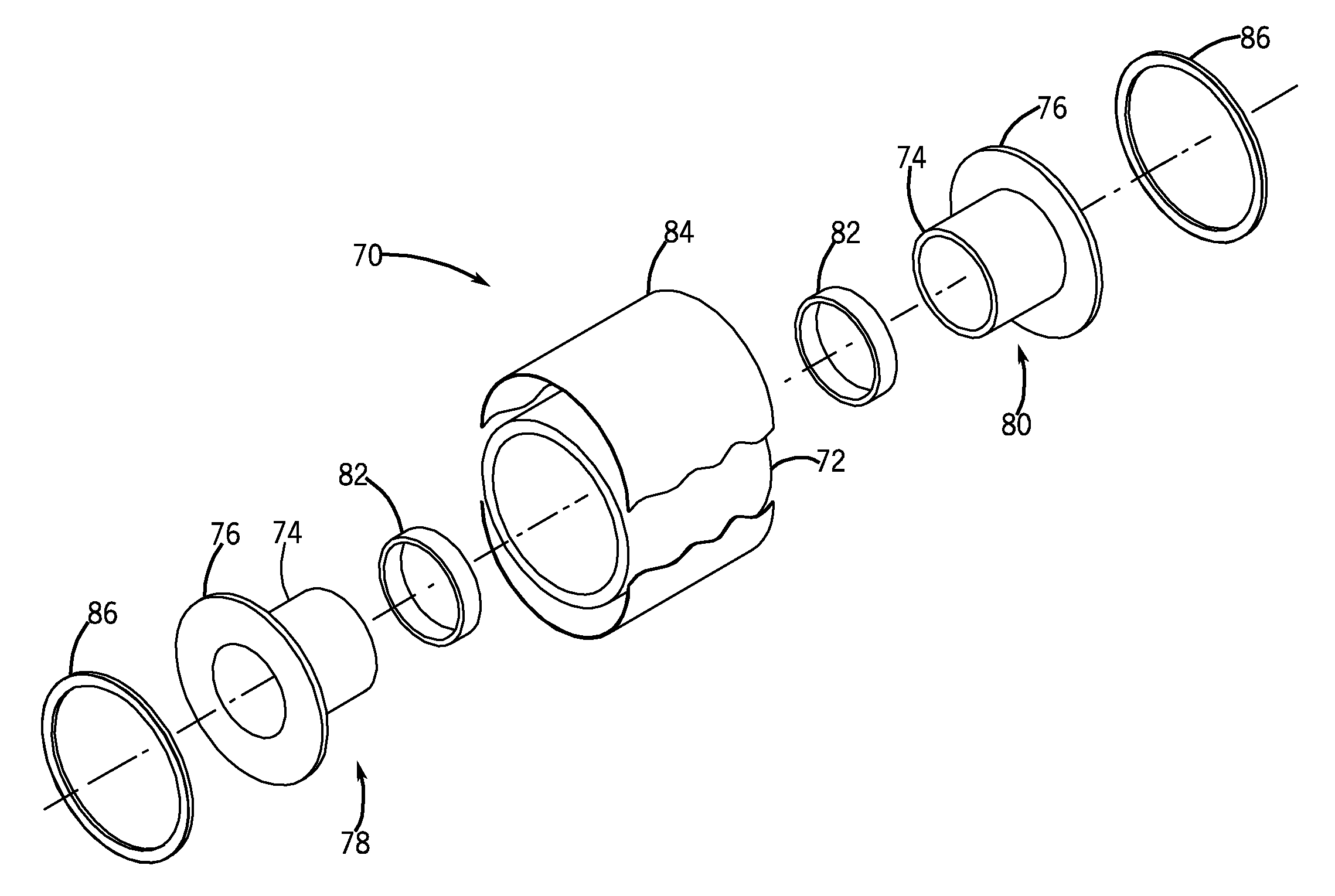
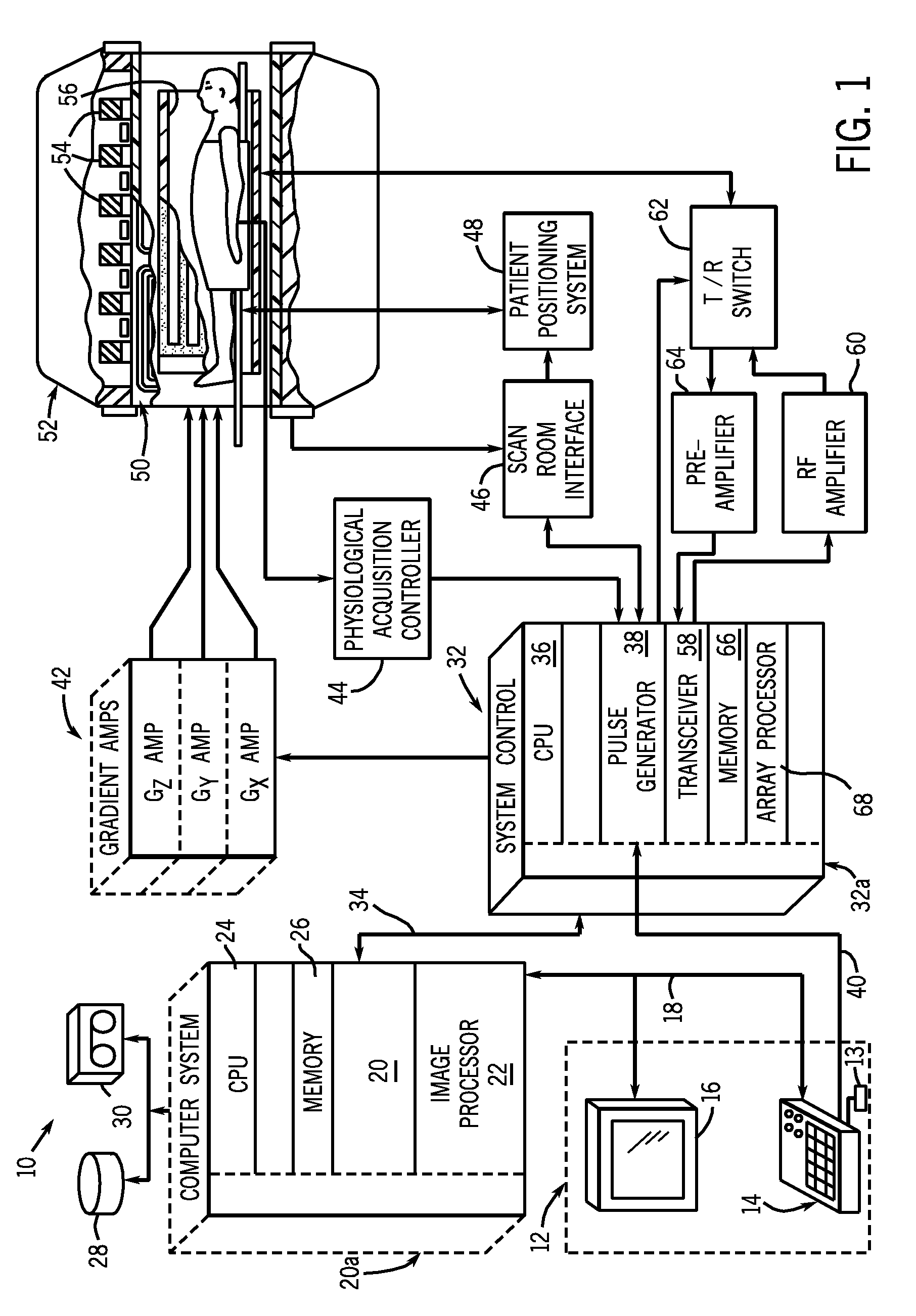
[0020]Referring to FIG. 1, the major components of a preferred magnetic resonance imaging (MRI) system 10 incorporating an embodiment of the present invention is shown. The operation of the MR system is controlled from an operator console 12 which includes a keyboard or other input device 13, a control panel 14, and a display screen 16. The console 12 communicates through a link 18 with a separate computer system 20 that enables an operator to control the production and display of images on the display screen 16. The computer system 20 includes a number of modules which communicate with each other through a backplane 20a. These include an image processor module 22, a CPU module 24 and a memory module 26, known in the art as a frame buffer for storing image data arrays. The computer system 20 is linked to disk storage 28 and removable storage 30 for storage of image data and programs, and communicates with a separate system control 32 through a high speed serial link 34. The input de...


PUM

PropertyMeasurementUnit
temperatureaaaaaaaaaa
magnetic resonance imagingaaaaaaaaaa
MRIaaaaaaaaaa

Abstract

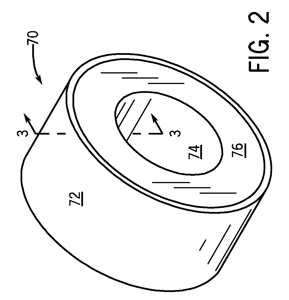
A vacuum vessel assembly includes an inner cylinder and an outer cylinder formed of a material in which eddy currents are substantially not produced. The inner cylinder includes a first and second half having an annular flange thereon. A plurality of metal interfaces are connected to the inner cylinder and the outer cylinder. The plurality of metal interfaces bond the first half and second half of the inner cylinder and also bond the inner cylinder to the outer cylinder.

Description

BACKGROUND OF THE INVENTION[0001]The invention relates generally to a magnetic resonance imaging (MRI) system and more particularly to a low eddy current vacuum vessel for enclosing a superconducting magnet in the MRI system and a process for manufacturing the vacuum vessel.[0002]MRI systems utilize superconducting magnets to generate a strong, uniform magnetic field within which a patient or other subject is placed. Magnetic gradient coils and radio-frequency transmit and receive coils then influence gyromagnetic materials in the subject to provoke signals that can be used to form useful images. Other systems that use such coils include spectroscopy systems, magnetic energy storage systems, and superconducting generators.[0003]In use with MRI, a superconducting magnet is disposed in a vacuum vessel that insulates the magnet from the environment during operation. The superconducting magnet also has a coil support structure to support the coil in a cooling mass and a helium vessel fo...

Claims


Application Information

Patent Timeline
Patent Type & Authority Patents(United States)
IPC IPC(8): G01V3/00
CPCG01R33/3804G01R33/3806G01R33/3815H01F6/04G06Q30/02Y10T29/49826H01F6/00H01F2027/348F17C13/007
Inventor HUANG, XIANRUITHOMPSON, PAUL S.
Owner GENERAL ELECTRIC CO
Why Eureka
Try Eureka