Method of repairing a rail

a rail and rail technology, applied in the field of rail rail repair, can solve the problems of non-destructive defects, defects that cannot be identified, and rail rails may be manufactured with internal defects, so as to minimize labor and reduce the amount of tim

Inactive Publication Date: 2009-04-21
HOLLAND CO
View PDF9 Cites 21 Cited by
  • Summary
  • Abstract
  • Description
  • Claims
  • Application Information

AI Technical Summary

Benefits of technology

[0025]In order to address the problem in the prior art of a fusion line of high hardness in the weld immediately adjacent a zone of low hardness in the rail, when graphed showing a dramatic valley and then peak before hardness levels, welding is accomplished in the invention with the use of a higher carbon welding electrode. While the problem in the prior art of alloyed steel of the migration of the carbon from the rail to the weld results in high hardness to the point of brittleness in one zone and low hardness to the point of softness in an adjacent zone, the use of a welding electrode which produces a weld deposit having carbon content of about 0.2% to 1.0% provides adequate resistance to carbon migration to avoid loss to the point of the achievement of desirable strength and hardness properties.
[0039]The system provides a rail repair which minimizes the labor necessary to repair the defect while maintaining the ART.

Problems solved by technology

Railroad rails may be manufactured with internal defects or, as a result of wear-and-tear or fatigue, develop defects.
These defects are found using non-destructive test methods.
Many of these defects are located in the top portion (i.e. the web or head) of the rail.
The track is not designed to allow the rails to contract and expand in response to environmental temperature changes.
The ART must be controlled because too low of an ART can cause the rail to buckle when the CRT of the rail is too high and too high of an ART can cause the rail to pull apart when the CRT of the rail is too low.
Buckles and pull aparts cause unsafe conditions and can cause serious accidents.
Moreover, such welds are not clean as they can include numerous inclusions from the welding process.
The flash-butt welding process is typically more costly than a thermite process but produces a cleaner and stronger weld.
However, this method also requires the repair crew to transport a plug to the rail repair site and the section of the rail containing the defect away from the site.
This prevents the railroad from running revenue producing trains.
In the area of gas shielded arc welding of railroad rails, several approaches have been taught, although they have not necessarily met with functional success in the field.
This can, in turn, result in the migration of carbon from the rail as well as a change in microstructure and material properties.
Moreover, the welding process can introduce hydrogen (H2) into the final weld which has the effect of embrittling the weld material and causing a weld failure.
Using apparatus such as that taught in U.S. Pat. No. 6,396,020 and U.S. Application Publication No. 2002-170,884 or U.S. Pat. No. 5,605,283, strength variations across the weld fusion line are problematic.
While higher carbon content steel is known, forming that steel into welding electrode commercially is not accomplished.

Method used


Image

  • Method of repairing a rail
  • Method of repairing a rail
  • Method of repairing a rail

Examples


Embodiment Construction

[0051]While the present disclosure will be described fully hereinafter with reference to the accompanying drawings, in which a particular embodiment is shown, it is to be understood at the outset that persons skilled in the art may modify the disclosure herein described while still achieving the desired result. Accordingly, the description that follows is to be understood as a broad informative disclosure directed to persons skilled in the appropriate art and not as limitations on the present disclosure.

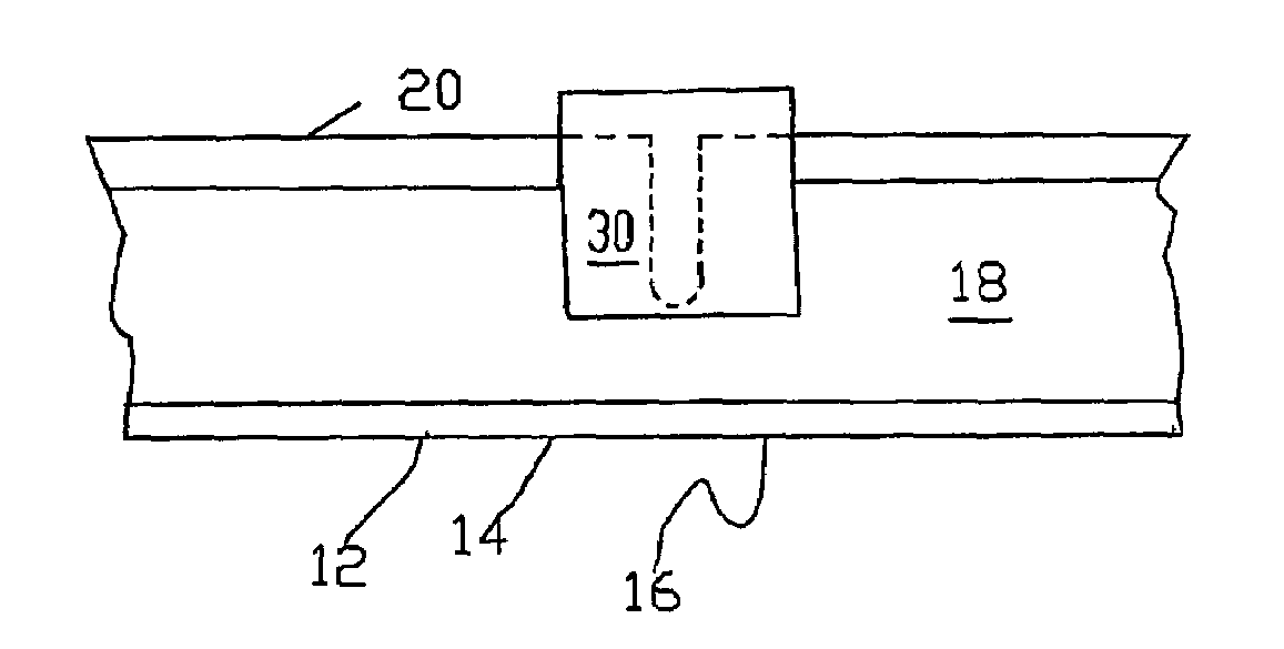
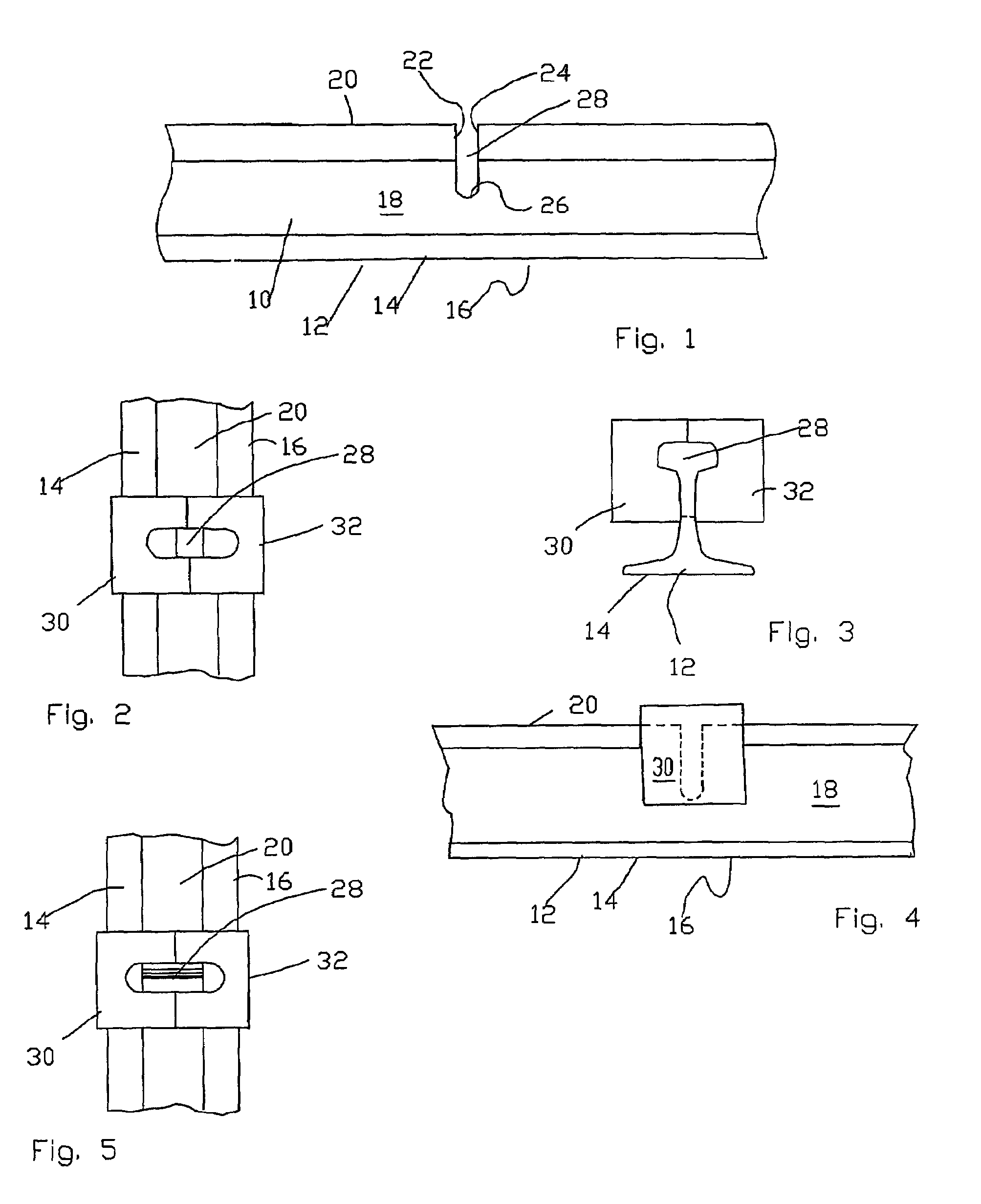
[0052]A railroad rail 10 is typically formed having a base 12 with opposed flanges 14, 16, an upstanding web 18 extending upward from the base 12 between the flanges 14, 16 and a head 20 at the top of the web. The repair system or method begins when a rail defect is identified and located, such as by using an ultrasonic rail-testing car. The ultrasonic rail-testing car can precisely locate and mark the area of the rail containing the defect. Additionally, manual testing of the defect...


PUM

PropertyMeasurementUnit
lengthaaaaaaaaaa
lengthaaaaaaaaaa
lengthaaaaaaaaaa

Abstract

A system or method of repairing railroad rails which includes a head, upright and base sections. The method includes at least the following steps: identifying and locating a defect in the rail, removing the defect by removing material from the rail surrounding the defect in at least the head section so as to form a void and a rail void interface while maintaining continuity of the rail, filling the void with molten metal having a high carbon content and causing the molten metal and the rail void interface to bond. The molten metal may be produced by gas shielded arc welding. The carbon content of the molten metal is near that of the rail to decrease carbon migration from the rails. High carbon welding electrode is used in the welding of high strength steel using gas shielded arc welding techniques whereby a plurality of beads of molten weld material join together rail ends or fill a slot in a rail for repair purposes, the high carbon electrode avoiding adjacent soft and brittle areas across a weld fusion line which result from migration of carbon from the carbon rich high strength steel to the lower carbon weld deposit.

Description

CLAIM OF PRIORITY[0001]This application claims priority from Provisional Patent application Ser. No. 60 / 564,763 filed Apr. 23, 2004 and PCT Patent application Ser. No. PCT / US03 / 24741 filed Aug. 8, 2003 which claims priority from Provisional Patent application Ser. No. 60 / 402,184, filed Aug. 9, 2002.BACKGROUND[0002]1. Field[0003]The invention relates to a method of repairing a railroad rail having a defect in the top portion of the rail by creating a cutout and filling the cutout with an appropriate material, preferably a high carbon content weld material.[0004]2. Description of Related Art[0005]Railroads have to maintain their track to ensure safe operation of trains. Some of this maintenance is centered around the repair of rail defects. Railroad rails may be manufactured with internal defects or, as a result of wear-and-tear or fatigue, develop defects. These defects are found using non-destructive test methods. The Federal Railway Administration (FRA) mandates periodic ultrasonic...

Claims


Application Information

Patent Timeline
Patent Type & Authority Patents(United States)
IPC IPC(8): B23K9/12B23K9/00B23K9/007B23K9/04
CPCB23K9/0026B23K9/044B23K35/3073B23K35/40B23K35/406C21D9/04B23K2201/26C21D1/06C21D1/26B23K2101/26
Inventor KRAL, RICHARD F.MAYHILL, SHANE A.JOHNSON, MATTHEW Q.ROVNYAK, MARK E.COOMER, DANIEL J
Owner HOLLAND CO
Why Eureka
Try Eureka