

Laser skin perforator
a skin perforator and laser technology, applied in the field of laser medical devices, can solve the problems of affecting the appearance of the skin, so as to facilitate the return of the deformed intermediate region and reduce the volume of the intermediate region
- Summary
- Abstract
- Description
- Claims
- Application Information
AI Technical Summary
Benefits of technology
Problems solved by technology
Method used
Image

Examples
Embodiment Construction
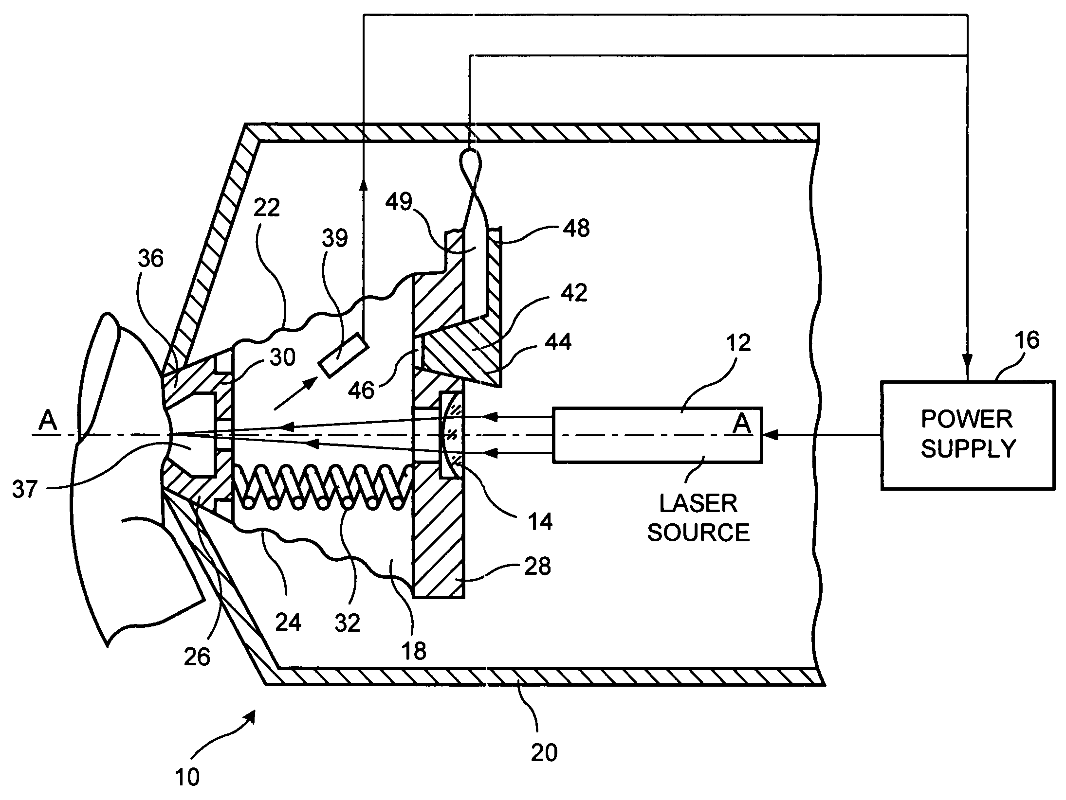
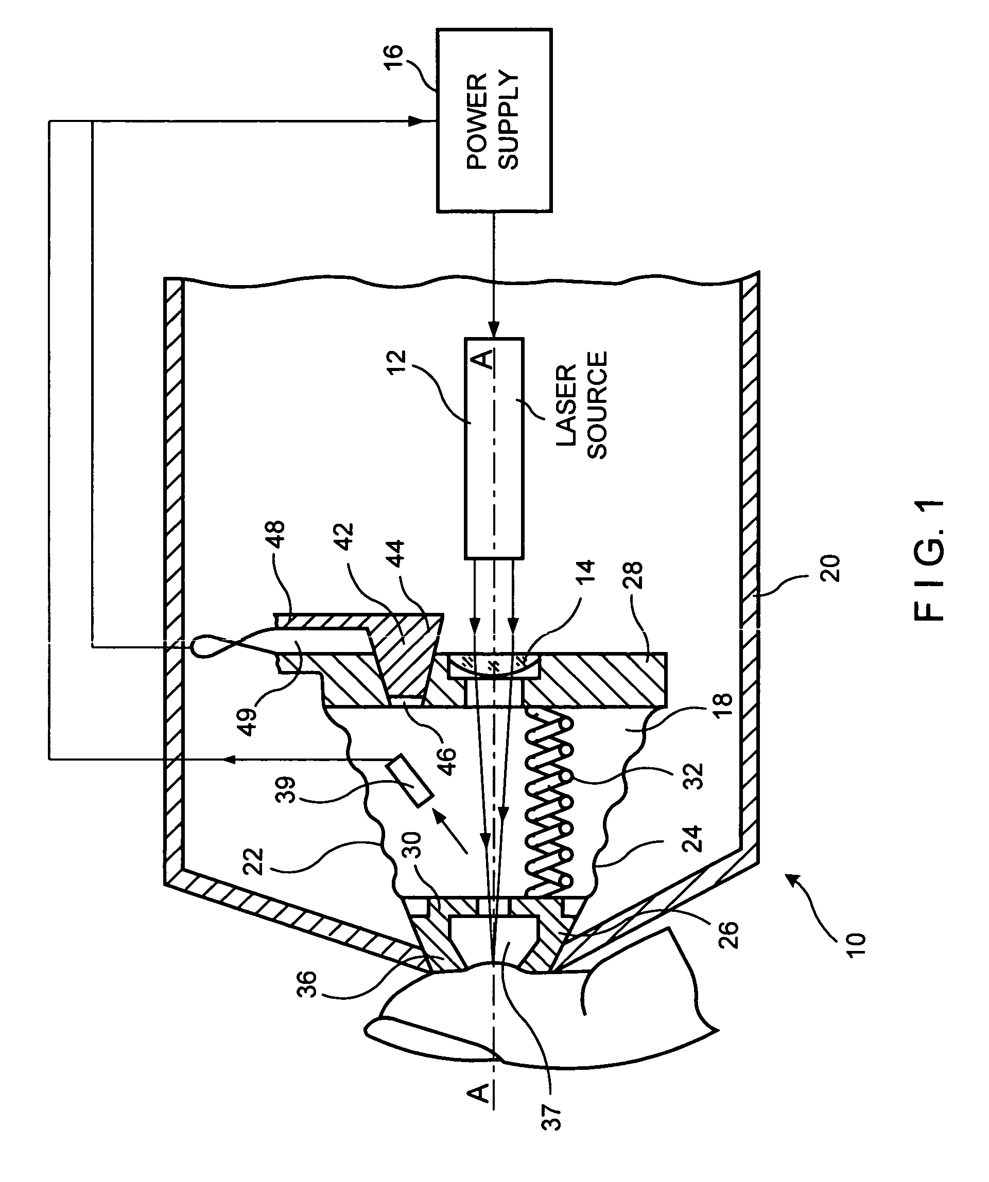
[0046]Reducing pain experienced by a patient during the skin perforation procedure is a complex undertaking which requires consideration of the following factors: safe and easy-to-use design of the apparatus, selection of the area of perforation, pre-treatment of the skin site prior to the perforation procedure and adjustment of the laser beam intensity. It is also necessary to define an optimal level of energy for each individual patient and provide proper focusing of the laser beam within the zone of perforation.
[0047]In minimizing of pain during the skin perforation, it is essential to reduce the density of the laser energy at a point of perforation and to minimize the size of a wound in a skin tissue of the patient, while keeping the amount of blood excretion at a constant level. In one embodiment of the invention this task is accomplished by stimulation of a blood flow within the skin site selected for perforation, so that even a small perforation may yield the required amount ...
PUM
| Property | Measurement | Unit |
|---|---|---|
| Area | aaaaa | aaaaa |
| Electric properties | aaaaa | aaaaa |
Abstract
Description
Claims
Application Information