Long life thin film battery and method therefor

a thin film battery, long-life technology, applied in the direction of flat cell grouping, cell components, sustainable manufacturing/processing, etc., can solve the problems of difficult to obtain extended life, difficult to expand on charging, and difficult to achieve barrier materials, etc., to improve hermetic seals and sealing methods, improve hermetic seals, and expand on charging

Inactive Publication Date: 2009-04-28
OAK RIDGE MICRO ENERGY
View PDF11 Cites 42 Cited by
  • Summary
  • Abstract
  • Description
  • Claims
  • Application Information

AI Technical Summary

Benefits of technology

[0008]With regard to the above, there is provided in one embodiment a method for improving the useful life of a thin film lithium-ion battery containing a solid electrolyte and an anode that expands on charging and long life batteries made by the method. The method includes providing a hermetic barrier package for the thin film battery that includes an anode expansion absorbing structure.
[0011]An advantage of the disclosed embodiments is that improved hermetic seals for thin film batteries having anodes that greatly expand on charging may be provided. While conventional thin film batteries containing lithium anodes and anodes that do not greatly expand on charging may use conventional hermetic seals, thin film batteries that have anodes that expand over about 200 percent of their height may benefit from the improved hermetic seals and sealing methods provided herein.

Problems solved by technology

Liquid electrolytes pose leakage problems and are often highly corrosive.
One of the challenges for thin film battery manufacturers is to provide a thin film battery that will have an extended life when exposed to an oxygen-containing atmosphere.
An extended life is particularly difficult to obtain with thin film batteries containing anode materials which are highly reactive with oxygen and / or water or water vapor.
However, such barrier materials have met with limited success.
However, exposure to air reduces battery life to a few days if oxygen permeation is not restricted to a sufficiently low level by a suitable barrier package.
While a polymer film may be able to accommodate the strain imposed by an expanding anode, a polymer film alone does not provide a sufficient barrier to oxygen and water vapor.

Method used


Image

  • Long life thin film battery and method therefor
  • Long life thin film battery and method therefor
  • Long life thin film battery and method therefor

Examples


first embodiment

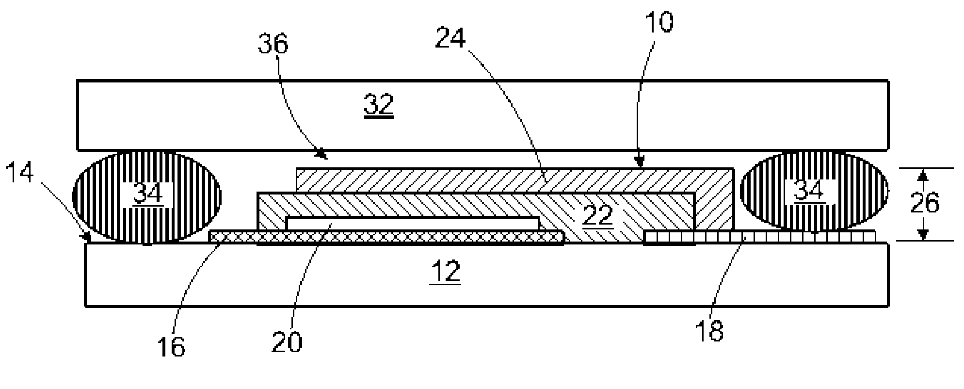
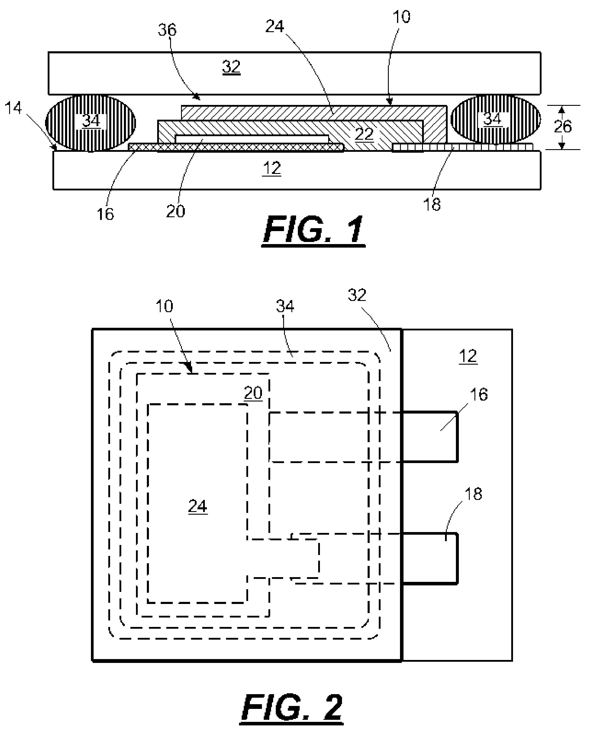
[0023]In a first embodiment, a thin film lithium ion battery 10 is provided on a solid substrate 12 having a support surface 14 as illustrated in FIG. 1. A cathode current collector 16 is deposited on the support surface 14 of the substrate 12. An anode current collector 18 is provided on the support surface 14 of the substrate in a spaced-apart location relative to the cathode current collector 16. A cathode 20 is deposited on a portion of the cathode current collector 16. A solid electrolyte 22 is deposited over the cathode 20, on a portion of the support surface 14 of the substrate 12, and on a portion of the anode current collector 18. Next, an anode 24 is deposited on the electrolyte 22 and a portion of the anode current collector 18. The components of the thin film battery are referred to herein as the thin film battery stack 26. The thin film battery stack 26 has a maximum thickness of less than about 7 microns measured from the support surface 14 to the highest point of the ...

second embodiment

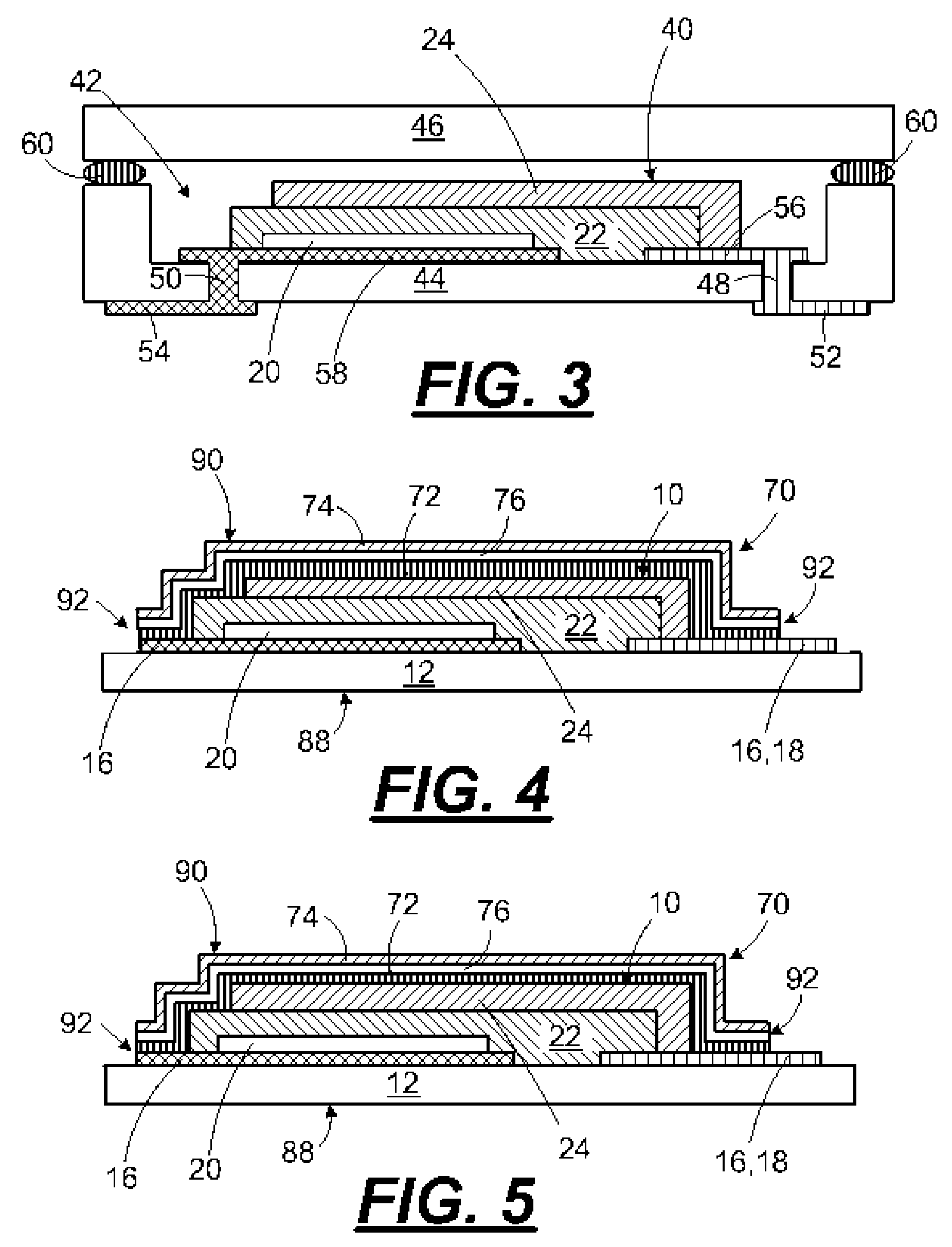
[0033]In a second embodiment, illustrated in FIG. 3, the battery 40 is deposited in a recessed area or pocket 42 of a substrate 44 and a cover 46 is hermetically sealed to the substrate 44 around a periphery of the pocket 42. In this embodiment, vias 48 and 50 may be etched through the substrate 44 to provide plated through-hole contacts 52 and 54 for the anode and cathode current collectors 56 and 58. The cover 46 may be sealed to the substrate 44 using brazing, laser welding, or an epoxy adhesive 60 as described above. In the alternative, a pocketed cover may be attached to a planar substrate by the foregoing methods. Chemical or dry etching techniques may be used to form the pocket 42 or cavity in the substrate 44 or pocketed cover.

[0034]In some applications, such as providing power for semiconductor diagnostic wafers, the thin film battery must be a thin as possible. Accordingly, an alternative type of hermetic package is illustrated in FIGS. 4 and 5. In this embodiment, a multi...


PUM

PropertyMeasurementUnit
melting temperaturesaaaaaaaaaa
thicknessaaaaaaaaaa
thicknessaaaaaaaaaa

Abstract

A method for improving the useful life of a thin film lithium-ion battery containing a solid electrolyte and an anode that expands on charging and long life batteries made by the method. The method includes providing a hermetic barrier package for the thin film battery that includes an anode expansion absorbing structure.

Description

FIELD[0001]The disclosure relates to thin film batteries and in particular to improved, long-life thin film batteries and methods for making long-life thin film batteries.BACKGROUND AND SUMMARY[0002]Thin-film rechargeable batteries have numerous applications in the field of microelectronics. For example, thin-film batteries may provide active or standby power for microelectronic devices and circuits. Active power source applications of the thin-film battery include, for example, implantable medical devices, remote sensors, wireless sensors, semiconductor diagnostic wafers, automobile tire sensors, miniature transmitters, active radio frequency identification (RFID) tags, smart cards, and MEMS devices. Standby power source applications of thin-film batteries include non-volatile CMOS-SRAM memory products such as memory ships for computers, sensors, and passive RFID tags.[0003]In a thin-film battery, a chemical reaction takes place between an anode and cathode by interaction of the an...

Claims


Application Information

Patent Timeline
Patent Type & Authority Patents(United States)
IPC IPC(8): H01M2/02H01M2/08H01M10/0525H01M10/0562H01M10/0585H01M10/36H01M50/11H01M50/119H01M50/121H01M50/124H01M50/193H01M50/197
CPCH01M2/0207H01M2/0212H01M2/0275H01M2/0277H01M2/0285H01M2/08H01M2/1022H01M4/38H01M4/382H01M10/0525H01M10/0562H01M10/0585H01M2/021Y10T29/4911H01M2/0287H01M6/40H01M2002/0297H01M2300/0068Y02E60/122H01M4/386H01M4/387Y02E60/10H01M50/124H01M50/131Y02P70/50H01M50/121H01M50/11H01M50/193H01M50/197H01M50/119
Inventor BATES, JOHN B
Owner OAK RIDGE MICRO ENERGY
Why Eureka
Try Eureka