
Supercharger with electric motor

a supercharger and electric motor technology, applied in the direction of positive displacement liquid engine, electric generator control, piston pump, etc., can solve the problems of reducing increasing the weight and the cost of the supercharger itself, and insufficient cooling of the rotor so as to prevent the efficiency of the electric motor from being lowered, suppressing the high temperature of the electric motor, and effective cooling of the stator and the rotor

Active Publication Date: 2009-05-12
IHI CORP
View PDF64 Cites 24 Cited by
  • Summary
  • Abstract
  • Description
  • Claims
  • Application Information

AI Technical Summary

Benefits of technology

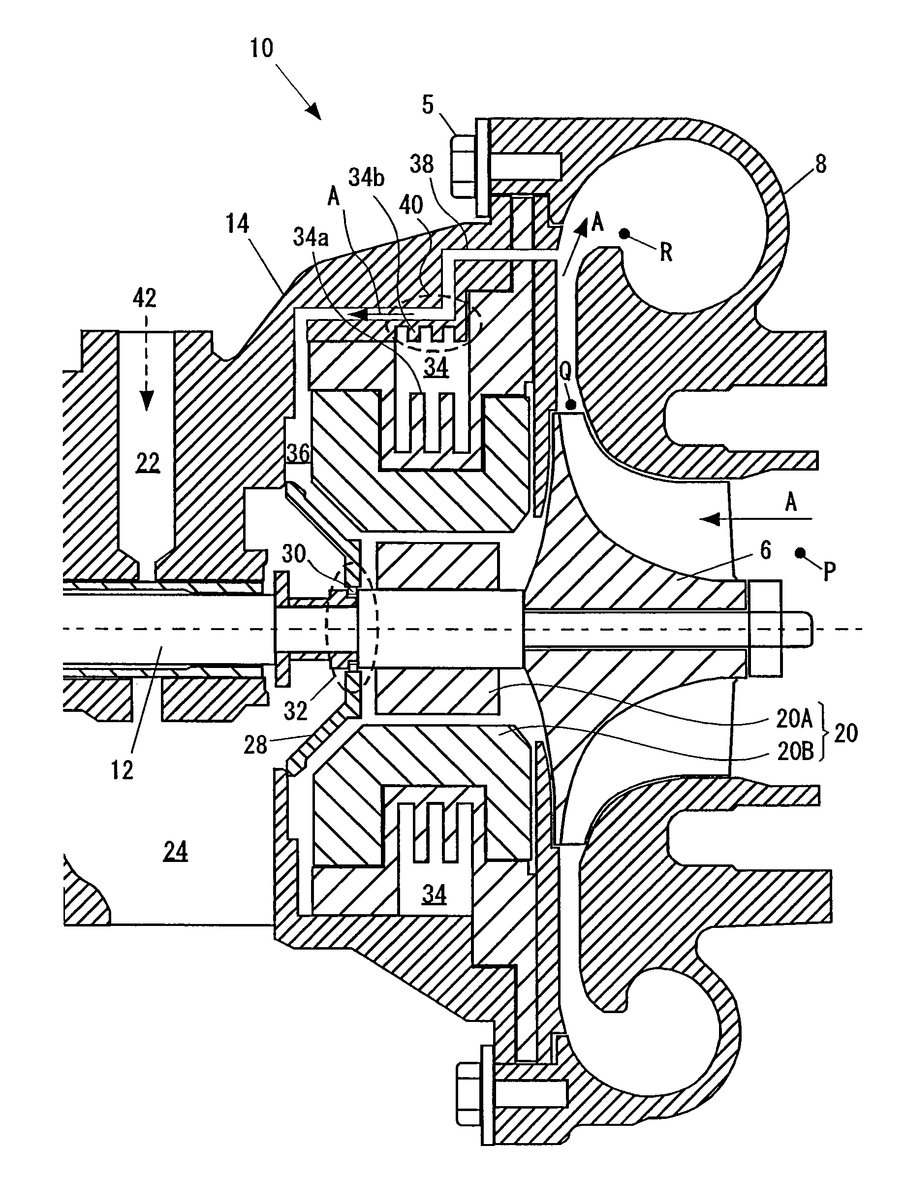
The present invention provides a supercharger with an electric motor that can effectively cool the stator and rotor of the motor without adding any external piping. This is achieved by introducing a part of the air in the outlet side of the compressor housing to the rotor of the motor and cooling it using a cooling structure portion. The cooling structure portion can be a cooling fluid flow path or a heat exchanging between the air and a lubricating fluid flowing within the center housing. This results in a reduction of the motor temperature, preventing permanent magnet demagnetization and maintaining motor efficiency.

Problems solved by technology

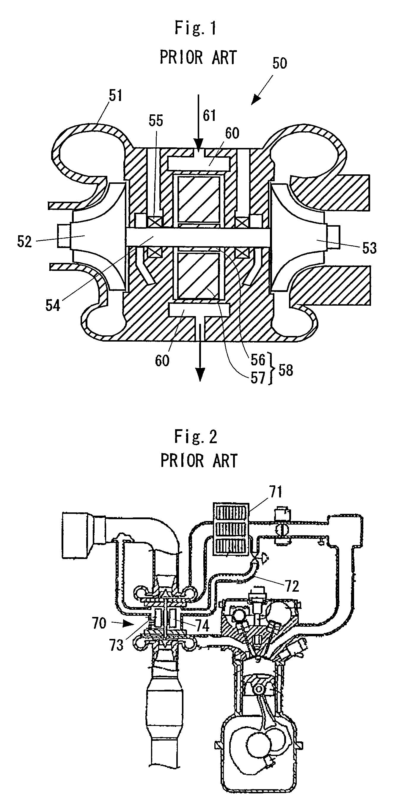
Accordingly, it is impossible to sufficiently cool the rotor of the electric motor, and there remain the problems that the permanent magnet is demagnetized and the efficiency of the electric motor is lowered.
However, in accordance with this method, since it is necessary to add an external piping such as the cooling gas introduction path 72, there is a problem that a weight and a cost of the supercharger itself are increased.

Method used


Image

  • Supercharger with electric motor
  • Supercharger with electric motor
  • Supercharger with electric motor

Examples


Embodiment Construction

[0033]A description will be in detail given below of a preferable embodiment in accordance with the present invention with reference to the accompanying drawings. In this case, the same reference numerals are attached to the common portions in each of the drawings, and an overlapping description will be omitted.

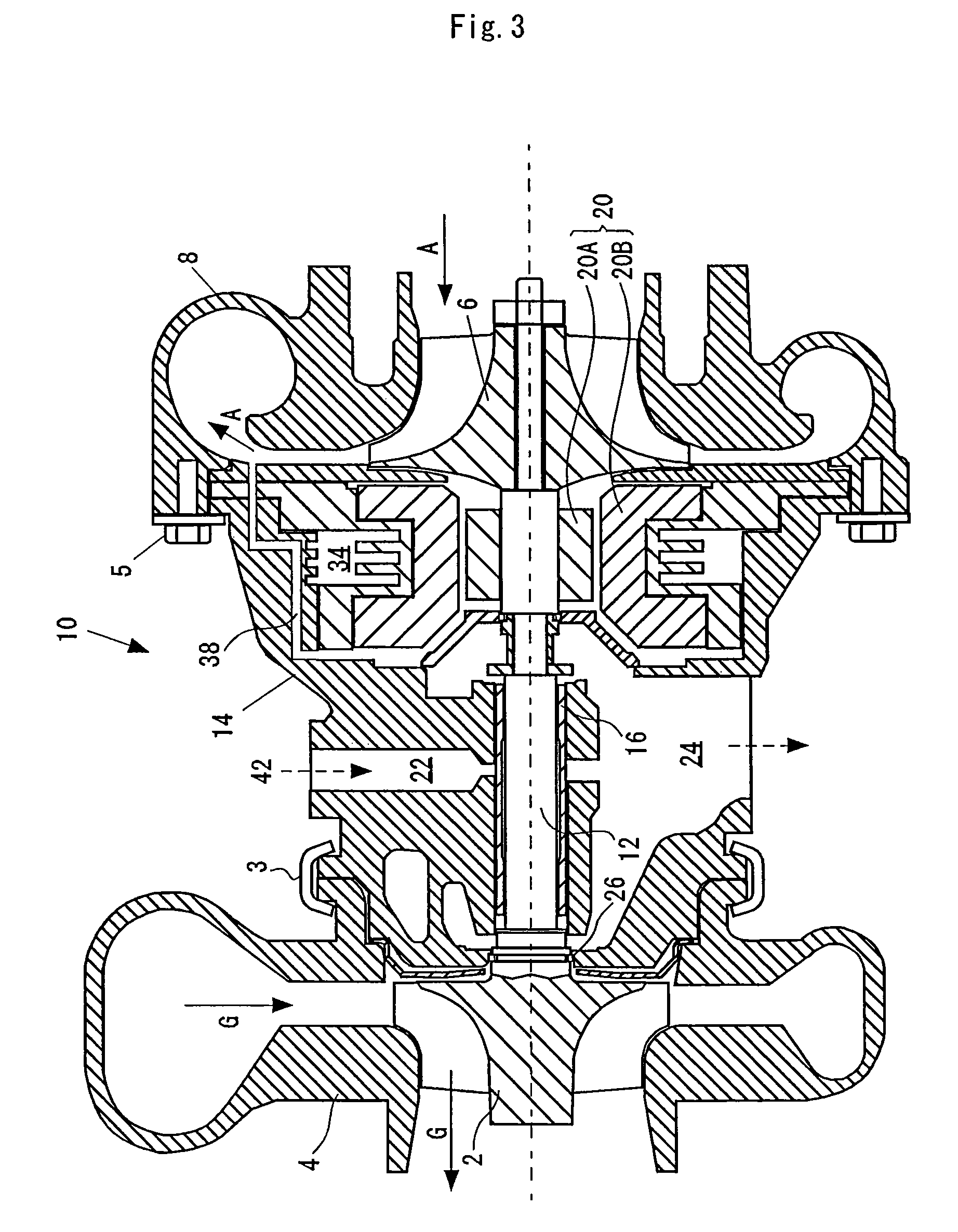
[0034]FIG. 3 is a cross sectional view of a supercharger with an electric motor in accordance with the embodiment of the present invention. As shown in FIG. 3, the supercharger 10 with the electric motor is constituted by constituting elements such as a turbine impeller 2, a turbine housing 4, a shaft 12, a compressor impeller 6, a compressor housing 8, an electric motor 20, a center housing 14 and the like.

[0035]In an exhaust passage side, there are arranged the turbine impeller 2 rotationally driven by an exhaust gas G of an internal combustion engine, and the turbine housing 4 surrounding the turbine impeller 2. In an intake side passage, there are arranged the compressor ...


PUM


Abstract

In a supercharger (10) with an electric motor in accordance with the invention, an inner side of the center housing (10) is provided with an air introduction path (38) introducing a part of a compressed air within the compressor housing (8) to the electric motor (20), and a cooling structure portion (40) cooling the air flowing through the air introduction path (38). The center housing (14) has a cooling fluid flow path (34) which is formed so as to surround the electric motor (20) and puts a cooling fluid for cooling the electric motor (20) in circulation inside. The cooling structure portion (40) is structured such as to be capable of heat exchanging between the cooling fluid and the air flowing through the air introduction path (38).

Description

[0001]This application claims priority from Japanese Patent Application No. 2005-227605, filed Aug. 5, 2005, the entire disclosure of which is incorporated herein by reference.BACKGROUND OF THE INVENTION[0002]1. Field of the Invention[0003]The present invention relates to a supercharger with an electric motor, which has an electric motor assisting a rotational drive of a compressor and is driven by an exhaust gas of an internal combustion engine and compressing an intake air so as to supercharge.[0004]2. Description of Related Art[0005]In order to improve a performance of an internal combustion engine, there has been widely used a supercharger (also called as “turbocharger”) driven by an exhaust gas of an internal combustion engine and compressing an intake air so as to supercharge. Further, there has been employed a supercharger with an electric motor in which an acceleration response or the like is improved by installing the electric motor on the same axis as a shaft of the superc...

Claims


Application Information

Patent Timeline
Patent Type & Authority Patents(United States)
IPC IPC(8): F02B33/44F02B37/00F02B37/10F02B37/12F02B37/14F02B37/16F04B39/02F04B39/06F04D23/00F04D31/00H02K9/19
CPCF02B37/04F02B39/005F02B39/10Y02T10/144Y02T10/12
Inventor SHIBUI, YASUYUKITAKAHASHI, YUKIO
Owner IHI CORP
Learn More