
Light emitting device having organic light-emitting element

a light-emitting element and light-emitting device technology, applied in the field of light-emitting devices, can solve the problems of reducing the illumination of the organic light-emitting element with time, and achieve the effects of preventing the degradation of the organic light-emitting element, preventing the penetration of moisture or oxygen, and enhancing the

Inactive Publication Date: 2009-05-12
SEMICON ENERGY LAB CO LTD
View PDF29 Cites 42 Cited by
  • Summary
  • Abstract
  • Description
  • Claims
  • Application Information

AI Technical Summary

Benefits of technology

[0025]In a light-emitting device according to the present invention, a periphery of an organic light-emitting element disposed between a first substrate and a second substrate is covered with a sealing agent of an ultraviolet absorbent dispersed in an ultraviolet curable resin. In a process of bonding the first substrate and the second substrate (sealing process), ultraviolet rays irradiated in curing the ultraviolet curable resin are shielded by the dispersed ultraviolet absorbent in a layer of the filled sealing agent so that no ultraviolet rays arrive at the organic light-emitting element. Therefore, degradation of the organic light-emitting element is prevented. In this way, the light-emitting element that has the organic light-emitting element with stable characteristics can be provided.
[0026]In addition, the effect of the sealing agent, preventing penetration of moisture or oxygen, can further enhanced by making the ultraviolet absorbent moisture-adsorbent or oxygen-absorbent.
[0027]By implementing the present invention, in a light-emitting device using an organic light-emitting element that has a top-emission structure, it is possible to obtain a light-emitting device that is able to prevent oxygen, moisture, and the like from arriving at an organic light-emitting element without disturbing displaying. In this way, the light-emitting device using the organic light-emitting element that has a sealing structure appropriate for a top-emission structure.

Problems solved by technology

By the way, in the above-mentioned organic light-emitting element, a material composing the organic light-emitting layer easily oxidizes or absorbs moisture due to an existence of oxygen or water to degrade, which results in a problem that the luminance of the organic light-emitting element lowers with time.

Method used


Image

  • Light emitting device having organic light-emitting element
  • Light emitting device having organic light-emitting element
  • Light emitting device having organic light-emitting element

Examples


embodiment mode 1

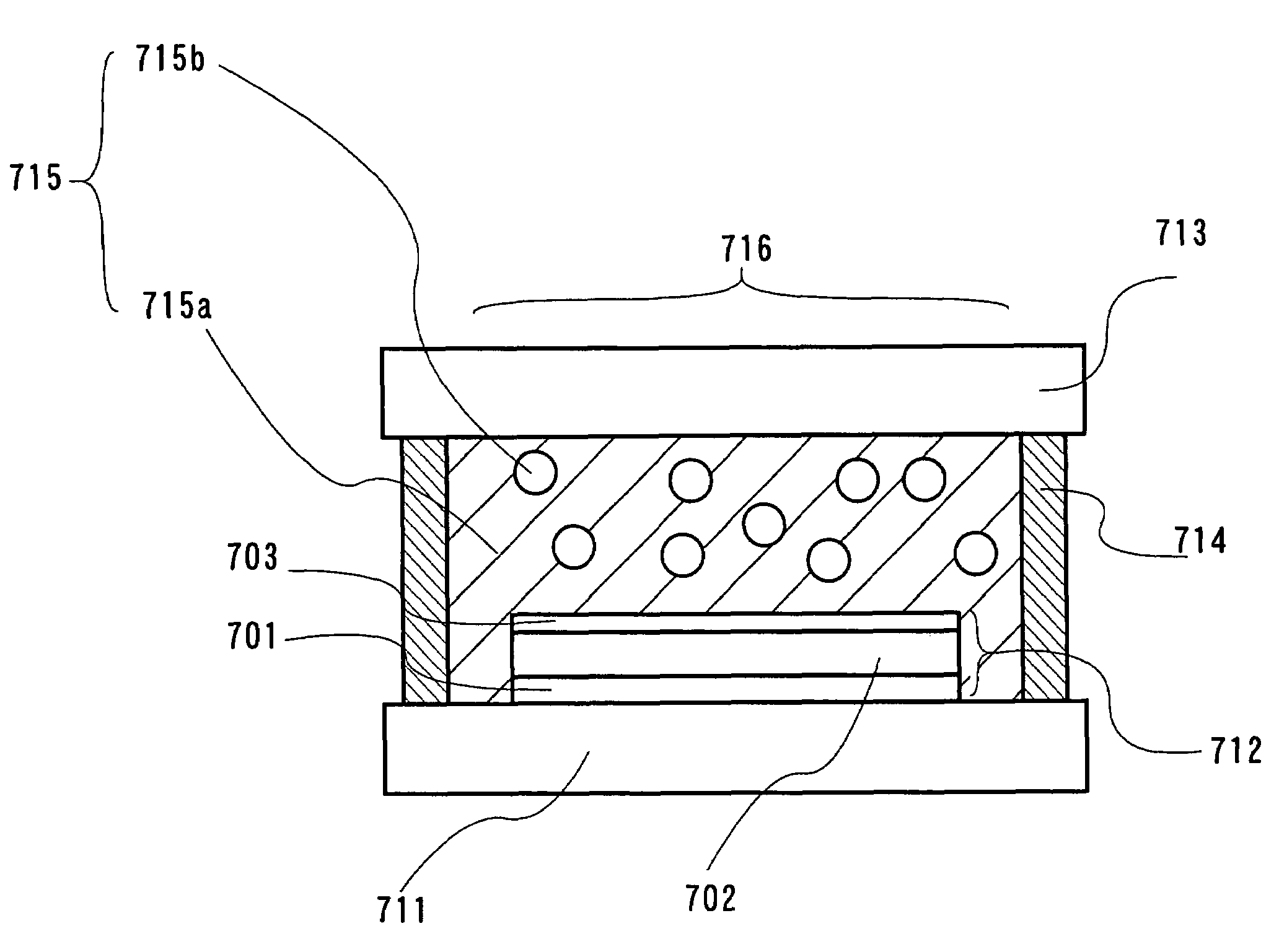
[0035]First, a form of a light-emitting device according to the present invention will be described with reference to FIG. 7. FIG. 7 has a structure in which a substrate (first substrate) 711 that has an organic light-emitting element 712 provided and an opposed substrate with transparency (second substrate) 713 are bonded, where the organic light-emitting element 712 comprises a first electrode 701, an organic light-emitting layer 702, and a second electrode with transparency 703. In bonding the substrate 711 and the opposed substrate 713, a region of a pixel portion 716 is covered with a second sealing agent with transparency 715, and the periphery is surrounded by a first sealing agent (which has a higher viscosity than the second sealing) including a gap material (such as a filler a fine particle) keeping an distance between the substrates. In other words, the structure is sealed with the first sealing agent 714 and the second sealing agent 715. As a content of the second sealin...

embodiment mode 2

[0038]The second sealing agent according to the present invention (715 in FIG. 7) will be described.

[0039]The second sealing agent has an ultraviolet absorbent dispersed in an ultraviolet curable resin in order to prevent ultraviolet rays to be irradiated from arriving at an organic light-emitting element.

[0040]As a method for preventing ultraviolet rays from arriving at an organic light-emitting element, there is also a method of forming a film over an organic light-emitting element as a layer shielding ultraviolet rays. However, it is difficult that to evaporate an inorganic ultraviolet-absorbent material (such as zinc oxide) by resistance heating, and deposition with a high-energy power source is necessary. In addition, since a high-energy particle collides with a substrate during evaporation, a manufactured organic light-emitting element is damaged. Although an ultraviolet-absorbent material exists also in organic materials, there is concern about deterioration of the ultraviole...

embodiment mode 3

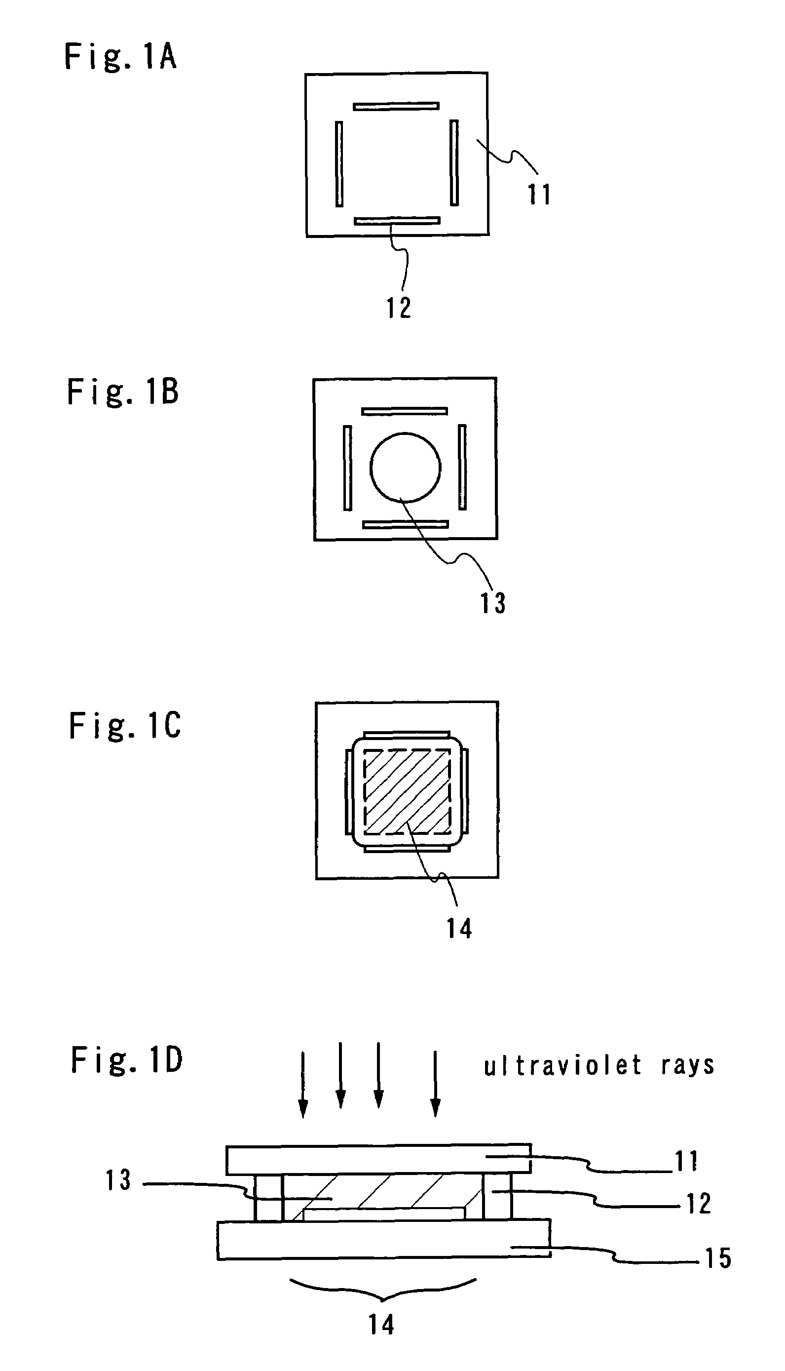
[0055]Here, a sealing process will be described with reference to FIG. 1.

[0056]First, with a dispenser system, a first sealing agent 12 is formed in a prescribed position on a second substrate 11 in an atmosphere of inert gas (FIG. 1(A)). As the translucent first sealing agent 12, one that includes a filler (diameter: 6 μm to 24 μm) and has a viscosity of 370 Pa·s is used. Further, the first sealing agent 12 can be formed by printing since the first sealing agent 12 has a simple sealing pattern.

[0057]Next, a second sealing agent 13 is dropped in a region surrounded by the first sealing agent 12 (however, four corners are openings). (FIG. 1(B))

[0058]Next, a first substrate 15 that has a pixel portion 14 provided and the second substrate 11 that has the sealing agents (the first sealing agent 12 and the second sealing agent 13) provided are bonded (FIG. 1(C)). It is preferable that annealing is performed in vacuum to perform degassing just before the pair of substrates are bonded with...


PUM


Abstract

In a sealing method of a top-emission organic light emitting element, in the case of using a method of filling with a sealing agent between a substrate mounted with pixels and an opposed substrate, the organic light-emitting element is degraded by ultraviolet rays when irradiation of the ultraviolet rays is performed toward the pixels in order to achieve ultraviolet curing of the sealing agent filling on the pixels. It is an object of the present invention to propose a method for avoiding this phenomenon to provide an organic light-emitting device with superior stability. In order for a sealing agent 13 filling on a pixel portion 14 to have a larger absorbance to ultraviolet rays, an ultraviolet-absorbent material is dispersed in a sealing agent to make an adjustment so that the absorbance of ultraviolet absorption wavelength of 400 nm or less becomes 1 or more.

Description

TECHNICAL FIELD[0001]The present invention relates to a light-emitting device that has an organic light-emitting element using an electroluminescent organic compound, and to an electronic equipment mounted with the light-emitting device as a part.BACKGROUND ART[0002]Recently, a light-emitting element using a material that emits light (electroluminescence) by applying an electric field (hereinafter, referred to as “EL material”) has been actively researched as a self light-emitting element. In particular, an element using an organic compound as the EL material (hereinafter, referred to as “organic light-emitting element”) has been attracting attention. Further, various light-emitting devices using the organic light-emitting element has been proposed, which is expected to be applied to displays.[0003]An organic light-emitting element has a structure in which a layer including an electroluminescent organic compound (hereinafter, referred to as “organic light-emitting layer”) is interpo...

Claims


Application Information

Patent Timeline
IPC IPC(8): H01J63/04H01L51/52H05B33/04H05B33/20
CPCH01L51/5237H01L51/5246H05B33/20H01L51/5206H01L51/5234H05B33/04H01L2251/5315H01L2251/5323H10K2102/3026H10K2102/3031H10K59/874H10K59/80524H10K59/8722H10K59/80518H10K59/875H05B33/145H10K50/8426H10K50/81H10K50/818H10K50/828H10K50/846
Inventor SHITAGAKI, SATOKOSEO, SATOSHINISHI, TAKESHI
Owner SEMICON ENERGY LAB CO LTD
Learn More