Position tracking device

a technology of positioning tracking and positioning device, which is applied in the field of motion tracking device, can solve the problems of not addressing the issue of accurate positioning tracking device, the inability of the apparatus to correlate the image data with the surface map of the patient, and the inability to accurately position the radiant therapy devi

Inactive Publication Date: 2009-05-12
LIPOSONIX
View PDF6 Cites 120 Cited by
  • Summary
  • Abstract
  • Description
  • Claims
  • Application Information

AI Technical Summary

Benefits of technology

[0022]Yet another objective of the present invention is to provide for a position tracking device that can accurately position a radiant therapy device in a three dimensional environment.
[0023]It is still further an objective of the present invention to provide for a position tracking device that can operate in conjunction with a medical device controller or a therapy procedure program to coordinate dosing in a two or three dimensional environment without relying on a physician for dosing.

Problems solved by technology

Few technologies exist at present for a physician to accurately map the surface area of a patient's epidermis, or correlate the surface map with a detailed three dimensional map of the tissue beneath the skin.
The necessity of being able to perform a medical procedure at a particular location precludes the utility of a device that accurately measures either surface movement and features, but makes imaging below the surface virtually impossible.
However this apparatus does not correlate the image data with a surface map of the patient's skin.
However the pointing device is designed for use with a computer system to serve as a pointing device, and not as a position tracking device.
The use of optical sensors and mechanical sensors as pointing devices does not address the issue of an accurate position tracking device.

Method used


Image

  • Position tracking device
  • Position tracking device
  • Position tracking device

Examples


first embodiment

[0041]In a first embodiment, the housing has a cylindrical form. The top section comprises a grip for a user to manipulate the device. The bottom section contains a medical device and a means for sensing the movement of the device over a patient. The bottom surface is preferably smooth and has a low coefficient of friction to facilitate an easy glide over the patient's skin. The bottom section also has a plurality of transmissible windows.

[0042]The primary transmissible window is a portal through which radiant energy of the medical device can affect the patient. The transmissible window is preferably solid, yet transparent to the energy emission of the medical device. The primary transmissible window is preferably made of a smooth material, so as to reduce drag and friction as the device moves over the patient.

[0043]The secondary transmissible windows allow optical sensors to image the patient's skin. Using well known principles established in the art of computer pointing devices, o...

second embodiment

[0049]In a second embodiment, the position tracking device has a housing having at least one transmissible window, and an aperture through the housing for slidably receiving a medical instrument. In this embodiment the housing has one or more transmissible windows used for the optical sensors as described above. However the medical device is not incorporated into the housing. Instead there is an aperture for slidably receiving a medical instrument, such as a syringe, biopsy needle, catheter insertion tool or the like. The aperture is adapted to receive medical instrument to be inserted into the patient.

third embodiment

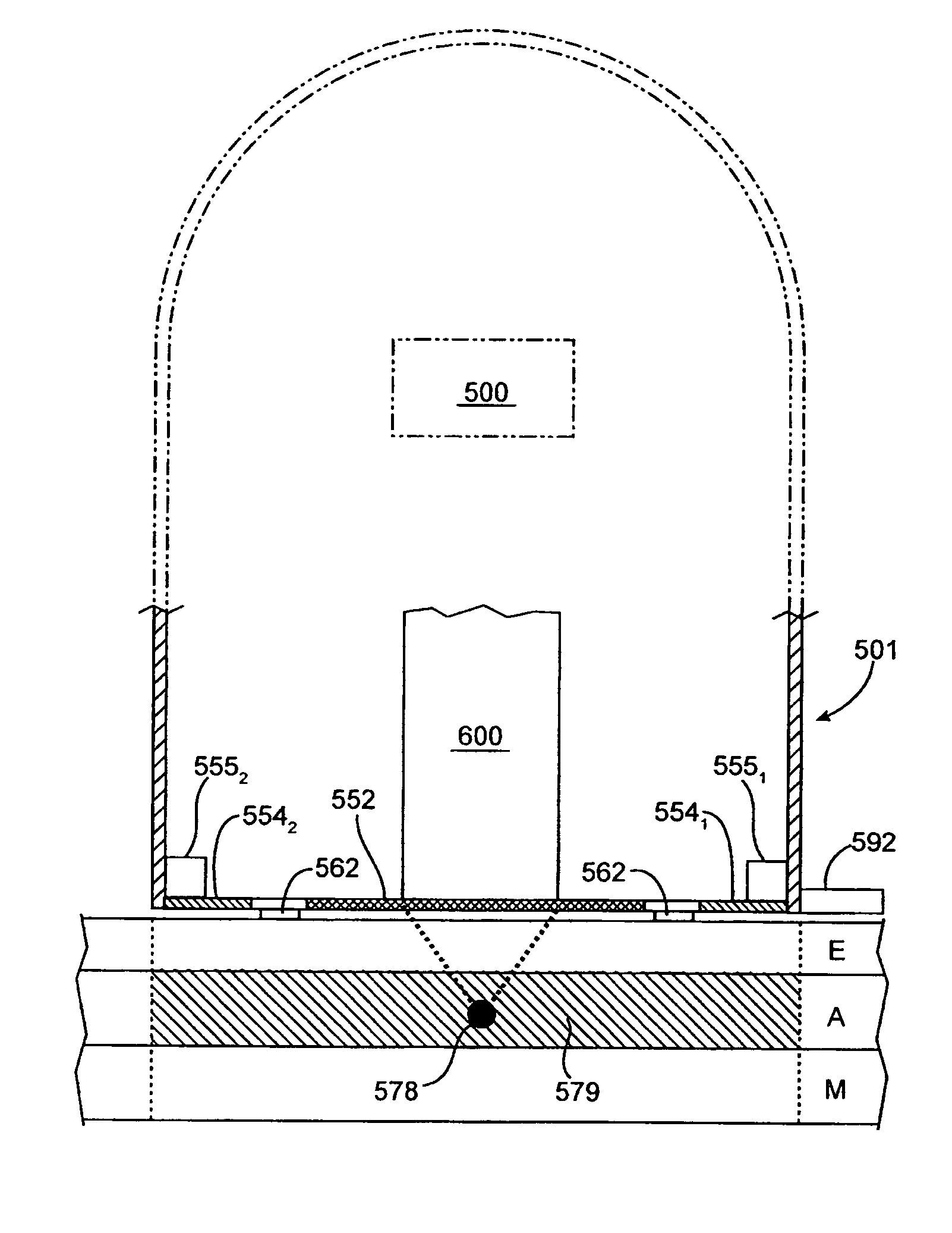
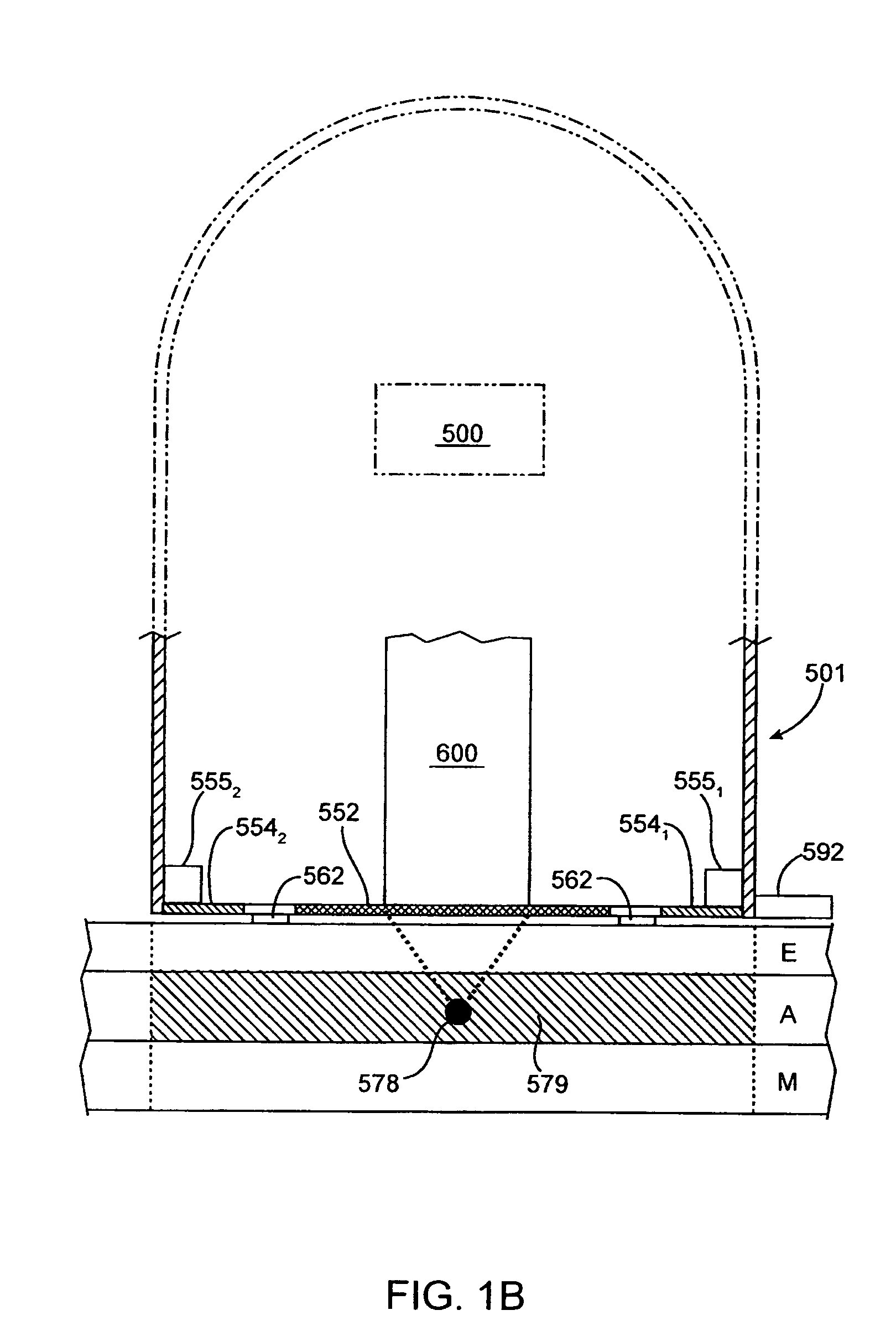
[0050]In a third embodiment the position tracking device has a housing having a primary transmissible window and at least one secondary transmissible window. The primary transmissible window allows an imaging sensor to scan or image the patient's tissue while the optical sensor(s) track the movement and position of the device through the secondary transmissible window(s). When the device is in the proper location a medical instrument may be inserted into the patient through the aperture. The medical imaging sensor combined with the optical sensors provide for a greater degree of accuracy in the placement of an insertion device than previously possible in a single device.

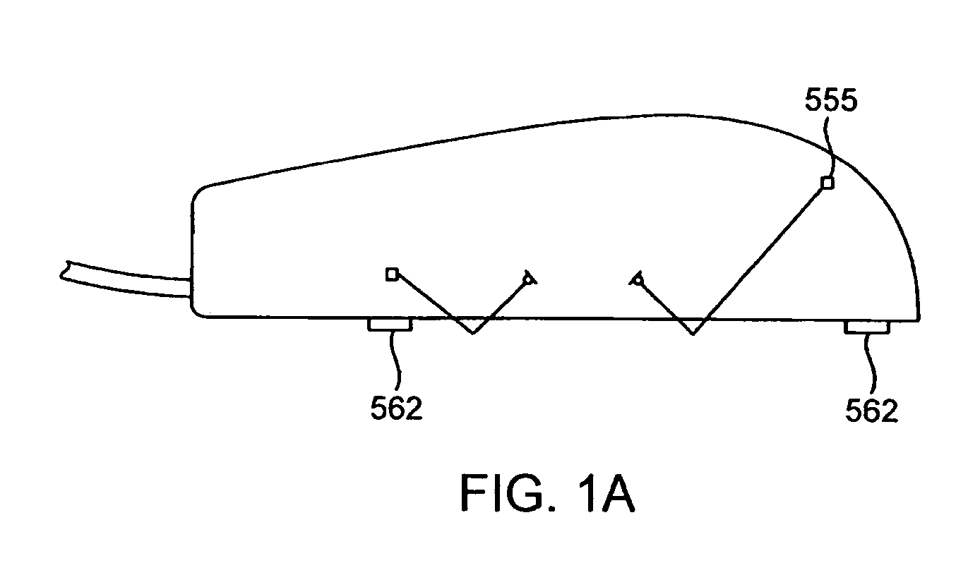
[0051]Turning now to the drawings, FIG. 1A illustrates an optical mice of the prior art Having a pair of optical sensors used for tracking changes in orientation. The mouse utilizes two optical detectors 5551, 5552 so a user can see on a computer screen the changes in orientation as he or she moves the computer point...


PUM


Abstract

A position tracking device is disclosed combining one or more optical sensors in a housing with a medical device. The medical device may be an insertion device or one that produces radiant energy. The device may utilize an on-board processor or an external processor to track position data generated by the optical sensors and correlate the treatment regime of the medical device. Alternative embodiments and methods of use are also described.

Description

CROSS-REFERENCES TO RELATED APPLICATIONS[0001]This application claims the benefit of prior provisional application No. 60 / 533,528, filed on Dec. 30, 2003, the full disclosure of which is incorporated herein by reference.[0002]The subject matter of the present application is related to that of the following applications: Ser. No. 10 / 750,370, entitled “Medical Device Inline Degasser”, Ser. No. 10 / 751,344, entitled “Articulating Arm for Medical Procedures”, Ser. No. 10 / 750,369, entitled “Disposable Transducer Seal”, 60 / 533,988, entitled “Method for Planning and Performing Ultrasound Therapy”; 60 / 534,036, entitled “Ultrasound Therapy with Hood Movement Control”; 60 / 533,958, entitled “Systems and Methods for the Destruction of Adipose Tissue”; 60 / 534,034, entitled “Component Ultrasound Transducer”; the full disclosure of each of these applications are incorporated herein by reference.BACKGROUND OF THE INVENTION[0003]1. Field of the Invention[0004]The present invention relates to a motion...

Claims


Application Information

Patent Timeline
Patent Type & Authority Patents(United States)
IPC IPC(8): G09G5/08A61B5/05A61B8/08
CPCA61B8/08A61B8/0841A61B8/4438
Inventor QUISTGAARD, JENS U.DESILETS, CHARLES S.ETCHELLS, TIMDARLINGTON, GREGORY PAUL
Owner LIPOSONIX
Why Eureka
Try Eureka