Fuser member

a fuser and coating technology, applied in the field of electrostatic apparatus and coated fuser members, can solve the problems of wrinkling artifacts, non-compatibility of fluoropolymer resins, and inability to adhere to heat-softened toner particles, and achieve good heat resistance, good non-adhesion toner, and little or no deterioration of layers.

Inactive Publication Date: 2009-05-19
MIDWEST ATHLETICS & SPORTS ALLIANCE LLC
View PDF13 Cites 11 Cited by
  • Summary
  • Abstract
  • Description
  • Claims
  • Application Information

AI Technical Summary

Problems solved by technology

One of the long-standing problems with electrostatographic fixing systems is the adhesion of the heat-softened toner particles to the surface of a fuser member and not to the receiver, known as offset, which occurs when the toner-bearing receiver is passed through a fuser system.
One known non-adhesive coating for fuser members comprises fluoropolymer resins, but fluoropolymer resins are non-compliant.
However, fuser members with a single compliant rubber layer absorb release oils and degrade in a short time leading to wrinkling artifacts, non-uniform nip width and toner offset.
Sintering of the fluoropolymer resin layer is usually accomplished by heating the coated fuser members to temperatures of approximately 500° C. Such high temperatures can have a detrimental effect on the silicone rubber layer causing the silicone rubber to smoke or depolymerize, which decreases the durability of the silicone rubbers and the adhesion strength between the silicone rubber layer and the fluoropolymer resin layer.
Dielectric heating is, however, complicated and expensive and the fluoropolymer resin layer may still delaminate from the silicone rubber layer when the fuser members are used in high-pressure fuser systems.
In addition, a fuser member made with a fluoropolymer resin sleeve layer possesses poor abrasion resistance and poor heat resistance.

Method used


Image

  • Fuser member
  • Fuser member
  • Fuser member

Examples


example 1

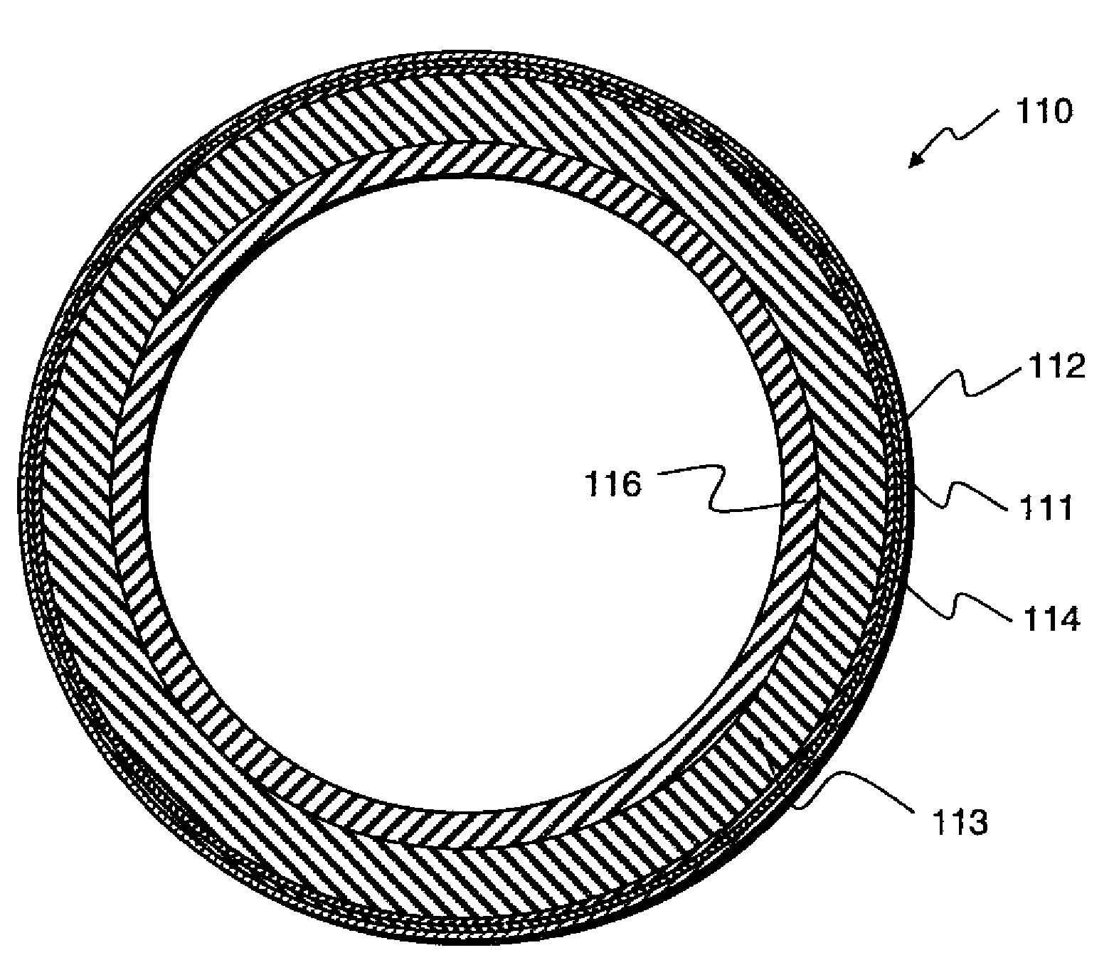
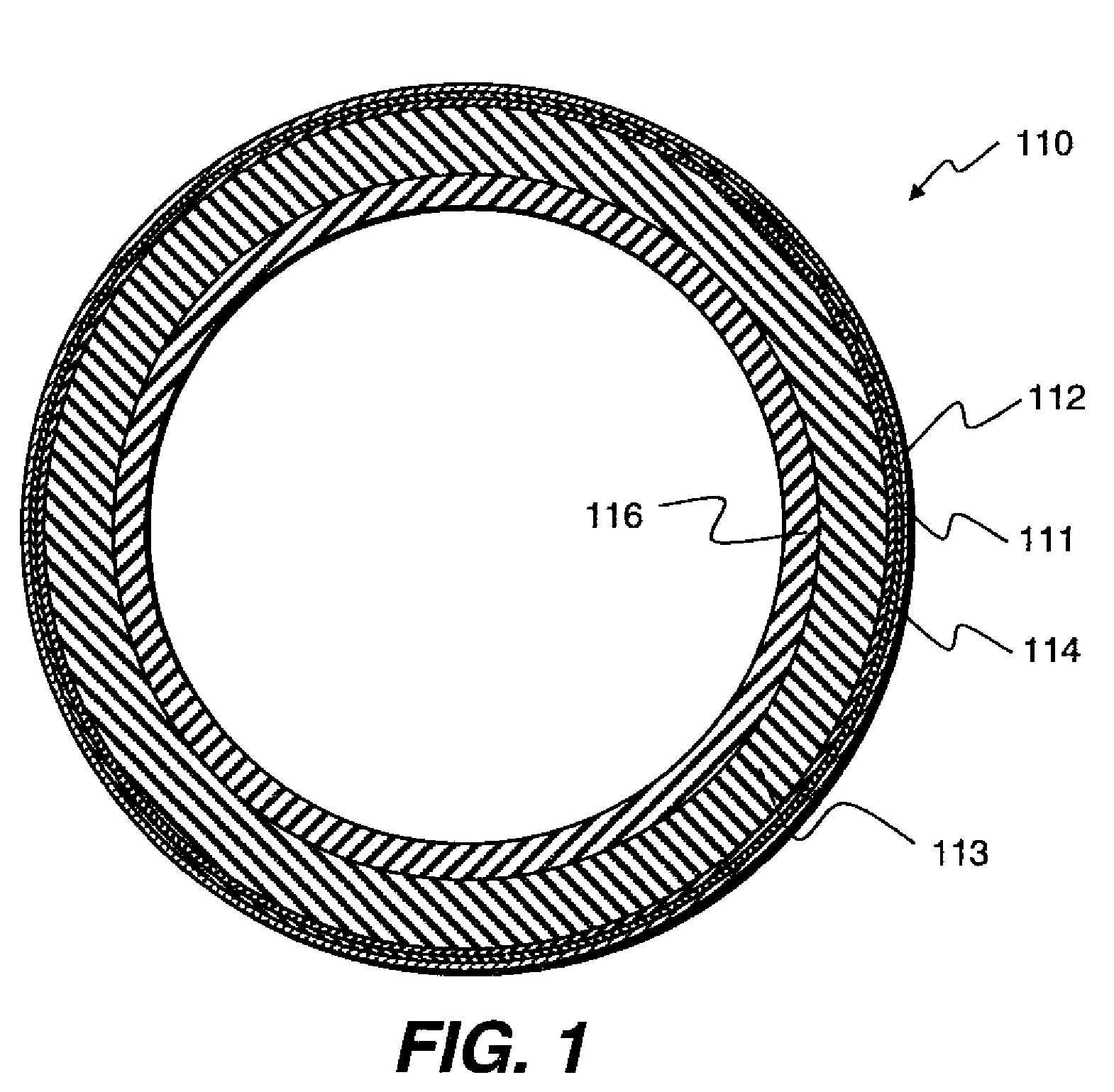
[0070]A coated roller including, in order, a support, a base cushion adhesion promoter layer and a silicone rubber layer, and a fluoroelastomer tie layer, a primer layer, a PFA fluoropolymer resin layer was prepared.

[0071]A steel cylindrical core with a 3.5 inch outer diameter and 15.2 inch length that was blasted with glass beads and cleaned and dried with dichloromethane was uniformly spray-coated with an adhesion promoter ShinEtsu X-33-176 to a uniform thickness of from 0.1 to 0.2 mil. The adhesion promoter was air dried for 15 minutes and placed in a convection oven at 325° F. for 45 minutes. A silicone base cushion layer is then applied to the treated core. The preferred addition cure silicone rubber X-34-1284 supplied by ShinEtsu Company is applied, for example, by injection-molding. The silicone rubber then cured 24 hrs at room temperature, and post cured 3 hrs at 200° C. in a convection oven. The resulting thickness of the base cushion layer was 220 mil. The fluoroelastomer ...

example 2

[0073]A coated roller including, in order, a support, a base cushion adhesion promoter layer and a silicone rubber layer, and a fluoroelastomer layer, a primer layer, a PFA fluoropolymer resin layer was prepared.

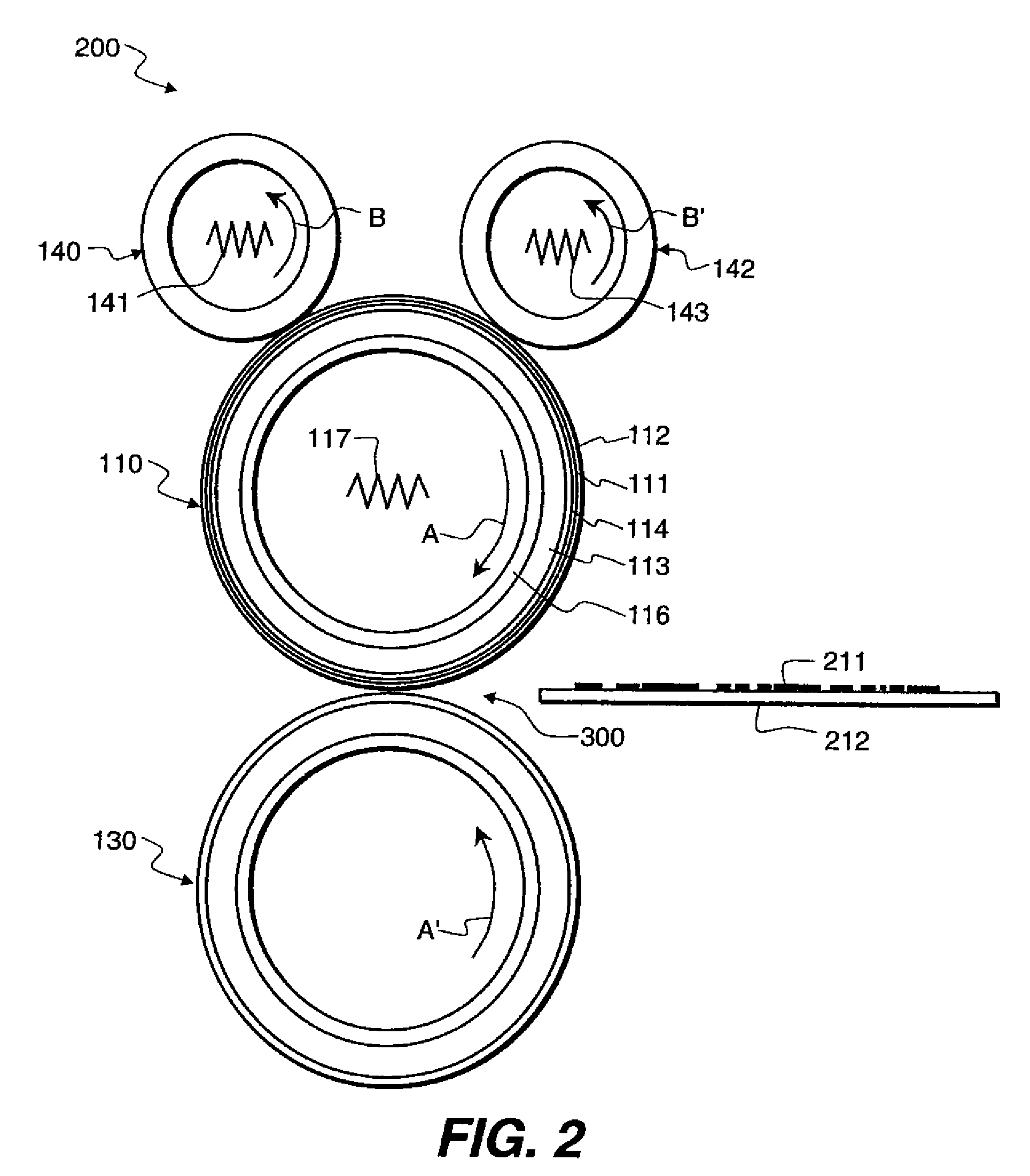
[0074]Example 1 was repeated, instead the top layer is cut and clamped into an Instron apparatus and the force required to peel the PFA top layer from the adjacent layer on the roller is measured, the life tests of the roller was performed by putting the roller in the NexPress 2100 machine.

example 3

[0075]A coated roller including, in order, a support, a base cushion adhesion promoter layer and a silicone rubber layer, and a fluoroelastomer layer, a primer layer, a PFA fluoropolymer resin layer was prepared.

[0076]Example 1 was repeated, instead the top layer is cut and clamped into an Instron apparatus and the force required to peel the PFA top layer from the adjacent layer on the roller is measured, the life tests of the roller was performed by putting the roller in the NexPress 2100 machine.

[0077]

TABLE 1Adhesion testExperi-Adhe-mentalPrim-BasesionExamplePFA topcoaterViton Tie LayerCushion(gmw)E-1855P322-5333FluoroelastomerX-34-1284263C-1855P322-3231NoneX-34-128472C-2855P322-32NoneNoneX-34-1284The minimum detectable load of adhesion was 32.


PUM

PropertyMeasurementUnit
thicknessaaaaaaaaaa
temperaturesaaaaaaaaaa
temperatureaaaaaaaaaa

Abstract

The fuser members of this invention include a core member that includes a rigid outer surface. An adhesion promoter layer comprising silane or epoxy silane coupling is disposed on the outer surface of the core member. A resilient layer comprising an elastomer is disposed on the adhesion promoter layer. A tie layer is disposed on the resilient layer, the tie layer being made of fluoropolymers, fluoroelastomers, fluorocarbon thermoplastic copolymers and mixtures thereof. A primer layer, disposed on the tie layer, comprising perfluoroalkoxy resin and trifluoroethylene-perfluoroethyl vinyl ether-perfluoroethylene vinyl phosphate or a mixture of perfluoroalkoxy resin and trifluoroethylene-perfluoroethylvinyl ether; and an outer layer of fluoropolymer resin made from polytetrafluoroethylene, polyperfluoroalkoxy-tetrafluoroethylene, polyfluorinated ethylene-propylene and blends thereof is disposed on the primer layer.

Description

CROSS-REFERENCE TO RELATED APPLICATIONS[0001]This application relates to commonly assigned, copending U.S. application: Ser. No. 11 / 472,918 “FUSER MEMBER”, U.S. application: Ser. No. 11 / 472,771 “FUSING MEMBER”, U.S. application: Ser. No. 11 / 472,919 “METHOD OF MAKING FUSER MEMBER” all said applications having been filed simultaneously herewith.FIELD OF THE INVENTION[0002]This invention relates to electrostatographic apparatus and coated fuser members and methods of making coated fuser members, and in particular to a conformable roller which includes an outermost fluoropolymer resin layer uniquely bonded to a silicone base cushion layer by means of a fluoroelastomer layer. More particularly, this invention relates to an improved multi-layer coating for fuser members and the method of making the multi-layer coated fuser members for oil-free color digital printing application.BACKGROUND OF THE INVENTION[0003]Known to the electrostatographic fixing art are various fuser members adapted t...

Claims


Application Information

Patent Timeline
Patent Type & Authority Patents(United States)
IPC IPC(8): B32B25/08B32B25/20B32B27/08G03G15/20
CPCG03G15/2057Y10T428/265Y10T428/269Y10T428/24355Y10T428/3154Y10T428/31544Y10T428/31663
Inventor CHEN, JIANN-HSINGPAVLISKO, JOSEPH A.JAO, SHYH-HUA E.SHIH, PO-JEN
Owner MIDWEST ATHLETICS & SPORTS ALLIANCE LLC
Why Eureka
Try Eureka