Vacuum heat insulator and apparatuses using the same

a heat insulator and vacuum technology, applied in the field apparatuses, can solve the problems of vacuum heat insulators, resin films, vacuum deterioration, etc., and achieve the effect of preventing the degradation of gas barrier properties

Inactive Publication Date: 2009-05-26
PANASONIC CORP
View PDF13 Cites 35 Cited by
  • Summary
  • Abstract
  • Description
  • Claims
  • Application Information

AI Technical Summary

Benefits of technology

[0010]A vacuum heat insulator of the present invention has a core material, and an enveloping member of a laminated structure including a heat seal layer, gas barrier layer, and protective layer. The heat seal layer is made of a resin having a melting point of at least 200° C., and the melting points of the gas barrier layer and protective layer are higher than that of the heat seal layer. Alternatively, the heat seal layer is made of a resin having a melting point above 100° C. and below 200° C., the melting point of the protective layer is at least 200° C., and fins are bent on a low-temperature side. Either of these structures can prevents degradation of gas barrier property in a high-temperature atmosphere of approx. 150° C. Thus, the heat-insulating property of the vacuum heat insulator can be maintained for a long period of time. An apparatus of the present invention includes a heat source or thermally insulated portion at temperatures above 100° C. therein, and the vacuum heat insulator insulates the heat.

Problems solved by technology

However, a conventional vacuum heat insulator using a general resin film as its enveloping member can only be used at temperatures lower than those slightly above 100° C. In a fixing unit of a copying machine, for example, an outer frame that houses the fixing part including a fixing roller and a delivery roller is provided using an engineering resin having heat-insulating property and heat resistance.
150° C. When the conventional vacuum heat insulator is installed in such a place, the degree of vacuum deteriorates at parts with insufficient heat resistance, and thus a predetermined heat-insulating property cannot be maintained for a long period of time.
Further, the enveloping member of the conventional vacuum heat insulator is made of a flammable film, such as nylon or polyethylene terephthalate, and does not have flame retardance.

Method used


Image

  • Vacuum heat insulator and apparatuses using the same
  • Vacuum heat insulator and apparatuses using the same
  • Vacuum heat insulator and apparatuses using the same

Examples


Embodiment Construction

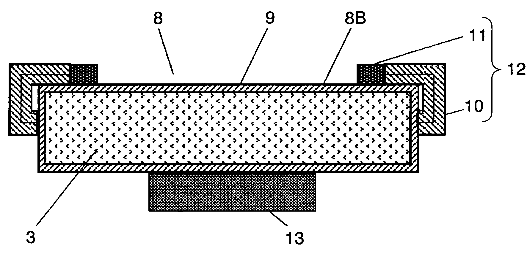
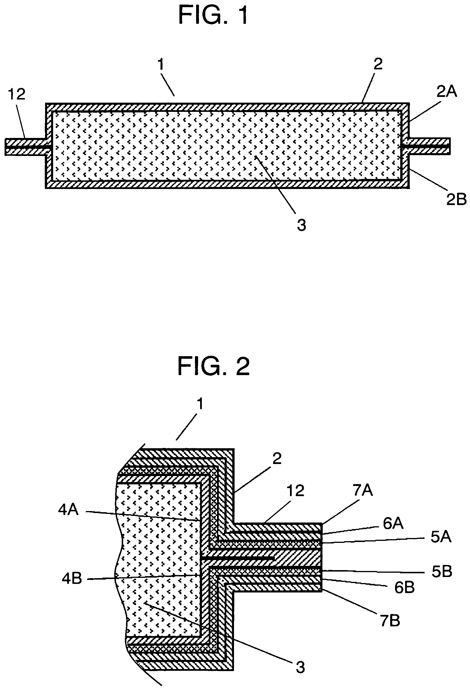
[0021]FIG. 1 is a sectional view of a vacuum heat insulator in accordance with an exemplary embodiment of the present invention. FIG. 2 is a sectional view of an essential part showing a fin of the vacuum heat insulator. Enveloping member 2 that is made of two sheets of laminated films (herein after referred to simply as films) 2A and 2B facing to each other covers core material 3. The inside of enveloping member 2 is evacuated and the periphery thereof is heat-sealed to form vacuum heat insulator 1.

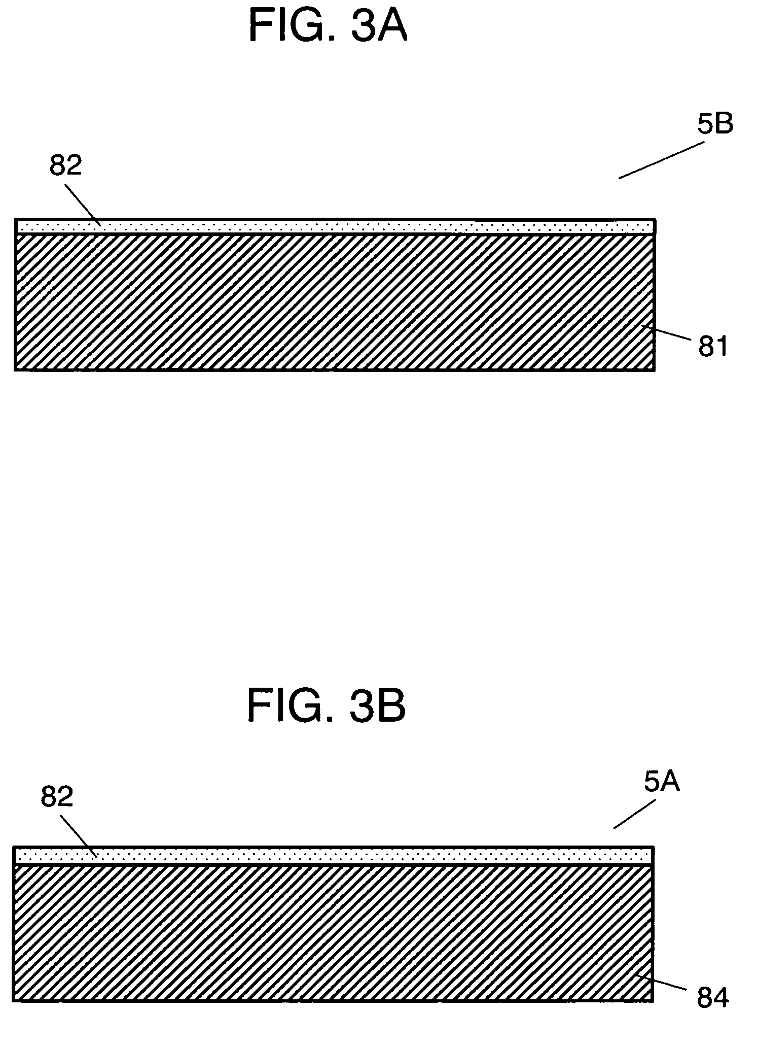
[0022]The two kinds of films 2A and 2B are composed of heat seal layers 4A and 4B, gas barrier layers 5A and 5B, first protective layers 6A and 6A, and second protective layers 7A and 7B, respectively.

[0023]Film 2A is used as a heat-insulating surface on a high-temperature side. For heat seal layer 4A, a polychlorotrifluoroethylene (50-μm-thick) having a melting point of 210° C. is used. Having a low melting point among fluorine resin films, polychlorotrifluoroethylene is easy to use and...


PUM

PropertyMeasurementUnit
temperatureaaaaaaaaaa
melting pointaaaaaaaaaa

Abstract

In a vacuum heat insulator, a heat seal layer of its enveloping member of a laminated structure is made of a film having a melting point of at least 200° C. Alternatively, the heat seal layer is made of a film having a melting point above 100° C. and below 200° C., and fins are bent on a low-temperature side. Either of these structures can inhibit a decrease in gas barrier property even in a high-temperature atmosphere of approx. 150° C. Thus, the heat-insulating property of the vacuum heat insulator is maintained for a long period of time. This vacuum heat insulator is preferable for an apparatus that has a heat source or a portion to be kept warm exceeding a temperature of 100° C.

Description

[0001]This application is a U.S. National Phase application of PCT International Application PCT / JP2004 / 004395.[0002]1. Technical Field[0003]The present invention relates to a vacuum heat insulator and apparatuses using the vacuum heat insulator. It particularly relates to heat insulation or keep warm in apparatuses having high-temperature portions, including printing machines such as a copying machine and laser printer, electronic equipment such as a computer, and further a water heater.[0004]2. Background Art[0005]A vacuum heat insulator is a heat insulator in which filling an enveloping member with foam resin, powder, or fiber material to form a core material and making the interior of the enveloping member vacuum considerably reduces its gaseous thermal conductivity. To maintain the heat-insulating property for a long period of time, the interior of the heat insulator is kept to vacuum.[0006]There is an electric kettle with considerably reduced power consumption for its thermal ...

Claims


Application Information

Patent Timeline
Patent Type & Authority Patents(United States)
IPC IPC(8): B32B1/06E04B1/80G03G15/20
CPCE04B1/803G03G15/2053Y10T428/231Y02B80/12F25D2201/14Y02A30/242Y02B80/10F16L59/06B32B15/06F25D23/06
Inventor TSUNETSUGU, KEISUKENAKAMA, HIROTO
Owner PANASONIC CORP
Why Eureka
Try Eureka