Method for producing a helically shaped, seamless multi-walled cylindrical article

a multi-walled cylindrical, seamless technology, applied in the direction of pipes, filament/thread forming, textiles and papermaking, etc., can solve the problems of wound materials, insufficient crushing strength to withstand higher inwardly directed forces, and increased crushing stress on the core, so as to smooth out possible imperfections.

Inactive Publication Date: 2009-06-23
PROTEUS
View PDF18 Cites 8 Cited by
  • Summary
  • Abstract
  • Description
  • Claims
  • Application Information

AI Technical Summary

Benefits of technology

[0021]It is a still further object of this invention to provide a multi-walled tubular structure of surprisingly improved strength characteristics as well as an improved method of making such and an improved apparatus for carrying out the improved method.
[0033]wherein the surface of the cooling drum may be tapered in a downstream direction such that, as the inner tubular member cools and thereby shrinks, the diameter of the cooling drum proportionally reduces an amount sufficient to permit the shrunk tubular structure to readily move across the cooling surface of the cooling drum and an amount sufficient to maintain cooling proximity between the inwardly directed surface of the inner tubular member of the extrudate and the cooling surface of the cooling drum, and thereby cooling and solidifying the inner tubular member and at least portions of the strut members that are proximate to the inner tubular member;
[0035]wherein the combination of the outer vacuum cooling means and the inner cooling drum are sufficient to cool the inner tubular member and the outer tubular member to substantially solid conditions, and sufficient to cool the struts an amount that renders them shape stable;
[0039]This structure will allow the cooling drum to be partially withdrawn into the passage in the die, so that during start-up only the downstream portion of the drum extends beyond the die. This enables the molten extrudate to be pulled over the cooling drum and guided into the downstream processing before it has the time to solidify and freeze on the cooling drum during start up. As the operation proceeds, the cooling drum can be moved in a downstream direction, that is, extending farther downstream of the extrusion die so that cooling of the interior tube becomes sufficient to solidify the inner tubular member during lined out operation of the instant method. That is, after startup, and when the system is running at lined out speeds, sufficient cooling takes place on the cooling drum to solidify the tubular structure which is then pulled off the drum. Because the system is running at lined out speeds, even though the interior tubular member is solidified on the cooling drum, it does not stick to the drum.
[0041]According to a preferred aspect of this invention, the cooling drum is rotatable about its streamwise axis. It has been found that in order for the structure to provide the maximum stiffness, the rib cells should be as symmetrical as possible. It has been found to be advantageous to provide rotational capability to the inner cooling drum. This enables the operator to have much better control over the relative rotation of the inner tubular element as compared to the outer tubular element. It is considered to be within the scope of this invention to rotate the inner tubular member at a different rotational speed than its next adjacent outer tubular member to accommodate the fact that the inner tubular member has a smaller diameter than the next outer tubular member. However, adjustability of the relative rotational speeds of the tubular members is a feature of this invention and so gives the operator excellent control.
[0043]A puller draws the multi-walled tube away from the cooling section of the instant apparatus while simultaneously twisting it about its longitudinal axis. In a preferred embodiment, the combination of pulling and twisting gives the tubular product a helical motion that causes the rib members (as well as the inner and outer tubular members) to be twisted into a helical shape. This is most desirable for several reasons. First, helical ribs provide both longitudinal and circumferential support to the plural tubular members of the product of this invention. Second, twisting the tube while it is still somewhat moldable tends to smooth out possible imperfections in the roundness of the tubular product.

Problems solved by technology

This tendency causes an even greater crushing stress on the core around which the shrink wrap film is wound.
However, it has been found that, although cardboard is very inexpensive and that is a very strong recommendation for its use, it does not have a crushing strength that is sufficient for it to withstand higher inwardly directed forces that are inherent in some wound materials, especially wound plastic film.
Therefore, so much plastic must be used to make a core of the desired crush resistance, that it is uneconomical.
The disadvantage of such cores is that they are generally quite expensive.
However, users have not generally returned the used cores.
The manufacturer can only amortize the cost of the core against a single use and thus must add the cost of the cores into his selling price of the material that is wound about the core.
This substantially increases the price at which the wound material must be sold whereby making it less competitive.
All in all, these prior art plastic cores have not met with any substantial degree of success and there is need for improvement in this technology.
Recently, a modified tubular core structure has been invented that has sufficient crushing strength to be useful in industrial applications, and employs little enough material to be economically viable.
Further, in appropriate situations, and with the correctly designated construction material, the helical configuration of the rib members adds a significant amount of longitudinal and radial bending stiffness.
It will be appreciated that making hollow tubes of this configuration on a commercial scale is a very difficult undertaking.

Method used


Image

  • Method for producing a helically shaped, seamless multi-walled cylindrical article
  • Method for producing a helically shaped, seamless multi-walled cylindrical article
  • Method for producing a helically shaped, seamless multi-walled cylindrical article

Examples


Embodiment Construction

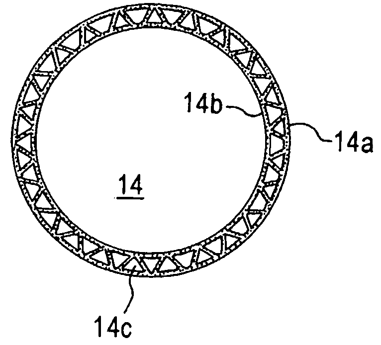
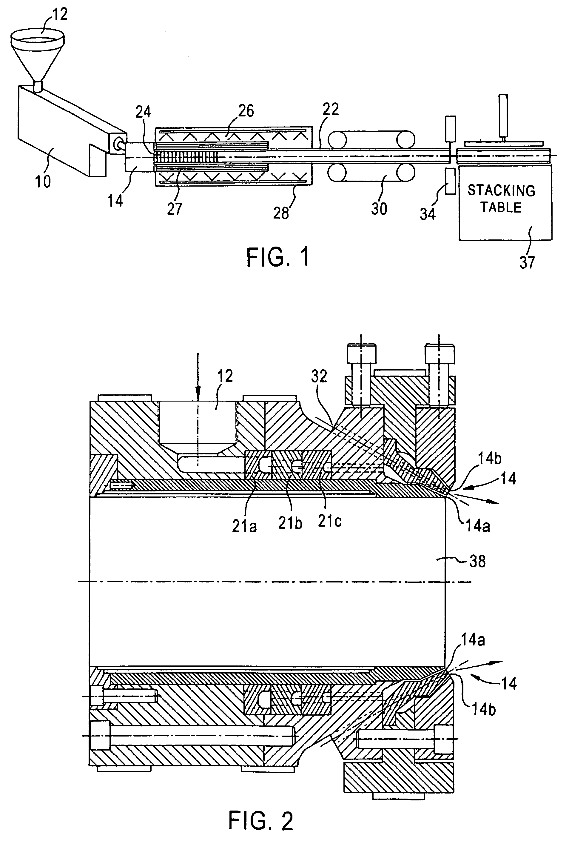
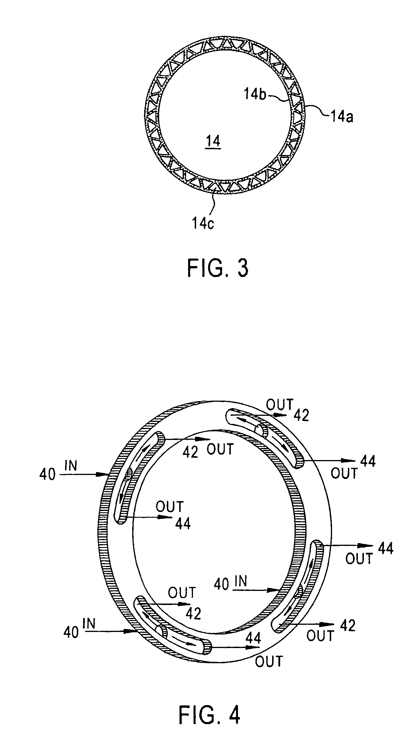
[0065]Referring now to FIGS. 1, 2, 3 and 7a, an extruder 10 is fed with a suitable material, such as a plastic resin, 12. The resin is melted in the extruder and passed through an extrusion die 14 of suitable configuration to form an extrudate 22 of appropriate size and shape. The extrudate 22 is a complex structure that is made up of an inner tubular element 16, an outer tubular element 18 and a plurality of struts 20a and 20b (see FIG. 7a) that are preferably, but not necessarily, angularly disposed. The extrudate structure 22 is passed through a vacuum chamber 28 in which it is pulled over a sizing sleeve and cooling drum 24 while being passed through an external coolant, such as a water spray, 26. Upon cooling and solidification, the extrudate product 22 is then pulled away from the cooling step and longitudinally twisted by a puller / twister 30 (see FIGS. 6, 8a, 8b, 9a, 9b, 13, and 14) such that the rib members assume a configuration that has a circumferential as well as a longi...


PUM

PropertyMeasurementUnit
diameteraaaaaaaaaa
angleaaaaaaaaaa
helical angleaaaaaaaaaa

Abstract

A method of making a composite tubular article made up of at least two concentric members, the outer of said members being tubular and the inner of said members being at least cylindrical and preferably tubular, and struts disposed in supporting and positioning orientation between the inner and outer members, by extruding a moldable material into the desired profile; stretching the inner tubular member over a cooling mandrel and disposing a cooling sleeve over the outer tubular member under conditions sufficient to solidify the article; twisting and longitudinally pulling the solidified article, so that it rotates over the cooling mandrel and inside the cooling sleeve while it is moving down stream across the cooling mandrel, whereby causing the extrudate to be twisted into a helical shape.

Description

[0001]This is a national stage application under 35 U.S.C. 371 of PCT / US 2002 / 24437, filed on Aug. 1, 2002, which claims the benefit of Provisional Application No. 60 / 309,494 filed on Aug. 3, 2001.BACKGROUND OF THE INVENTION[0002]This invention is related to a method of making certain kinds of tubing. It more specifically refers to a method of making a multiple walled tube, especially a two concentric walled tube with the two walls being radially spaced apart and having rib members in supporting relationship between and attached to the walls. The rib members of the composite tubular structure of this invention have been referred to as ribs, webs, struts and other identifying names. All of these members are intended to be included in this invention regardless of the name by which they are called. For ease of description and understanding, this invention will be described in relation to a two concentric walled tube. It will be understood that tubes with more than two concentric walls ...

Claims


Application Information

Patent Timeline
Patent Type & Authority Patents(United States)
IPC IPC(8): D01D10/00D01D5/24B28B11/08B23D21/04B26D1/60B26D3/06B26D3/16B26D9/00B29C48/10B29C48/11B29C48/32B29C48/355B29C53/14F16L9/19
CPCB23D21/04B26D1/60B26D3/06B26D3/16B26D9/00B29C47/0028B29C47/12B29C47/34B29C47/882F16L9/19B29C47/0023B29C47/0033B29C47/0038B29C47/0057B29C53/14B29C2793/0045B29C2793/0081B29C2793/009B29K2023/065B29K2025/00B29L2023/22B29L2024/006B29L2031/60B29C48/09B29C48/11B29C48/12B29C48/13B29C48/001B29C48/0018B29C48/0021B29C48/32B29C48/355B29C48/9115B29C48/914B29C48/905B29C48/10
Inventor HERRINGTON, F. JOHN
Owner PROTEUS
Why Eureka
Try Eureka