Waveforms for envelope tracking transmitter

a transmitter and waveform technology, applied in the field of radio frequency transmitters, can solve the problems of complex algorithm, high phase distortion, rapid gain and phase change, etc., and achieve the effect of optimal efficiency, and improving linearity and efficiency

Active Publication Date: 2009-06-23
NOKIA TECHNOLOGLES OY
View PDF15 Cites 68 Cited by
  • Summary
  • Abstract
  • Description
  • Claims
  • Application Information

AI Technical Summary

Benefits of technology

[0005]It is a primary object of the present invention to improve the linearity and efficiency of a power amplifier in a RF transmitter by keeping the amplifier in the linear and efficient operating point of each used power level. Ideally the operating point is such that when the output signal is close to the amplifier compression point, the efficiency is optimal. The signal should be below the amplifier compression point by a certain amount of back-off in order to maintain the linearity. The compression point is controlled by the supply voltage.

Problems solved by technology

While this prior art envelope tracking technique significantly improves the efficiency of the power amplifier in an RF transmitter, it does not deal with the rapid gain and phase changes when the supply voltage is very low.
Rapid phase changes result in high phase distortion, for example.
While this approach somewhat improves the efficiency of the power amplifi

Method used


Image

  • Waveforms for envelope tracking transmitter
  • Waveforms for envelope tracking transmitter
  • Waveforms for envelope tracking transmitter

Examples


Embodiment Construction

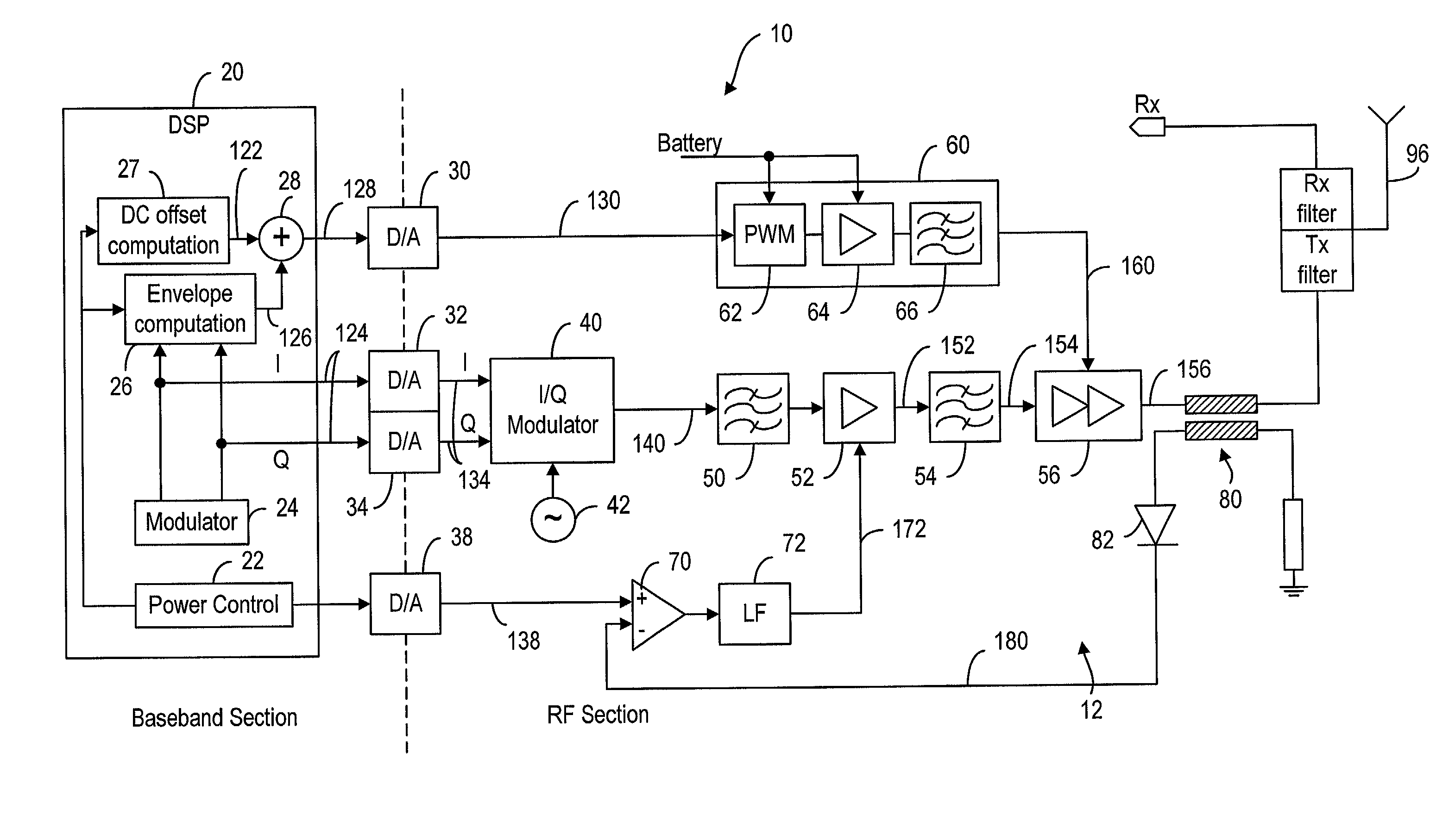
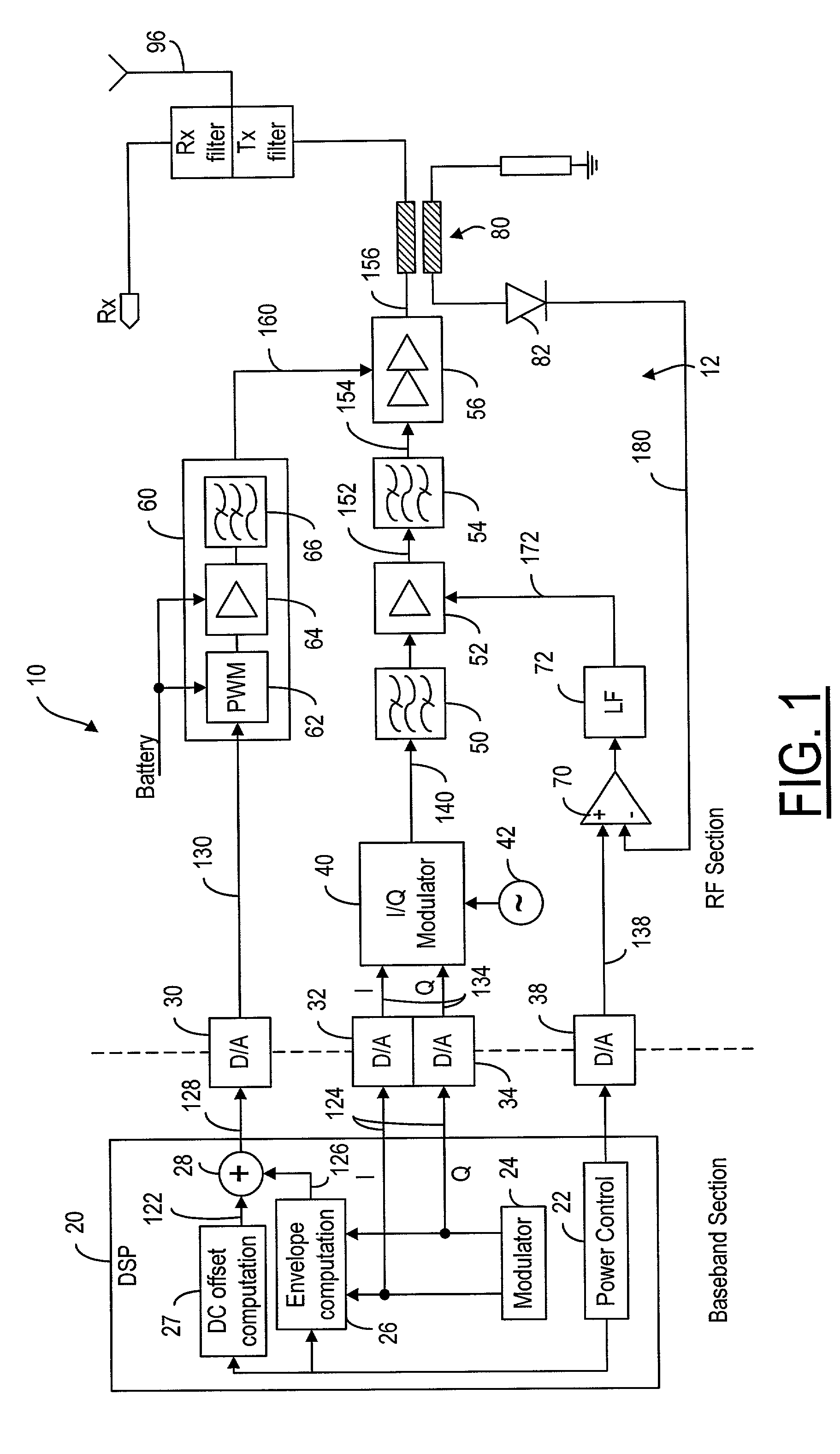
[0042]The envelope tracking transmitter 10 of the present invention, is illustrated in FIG. 1. As shown, the baseband section of the transmitter 10 comprises a digital signal processor (DSP) 20 for generating digital baseband data (I, Q) 124. The digital baseband data 124 is converted by digital-to-analog converters 32, 34 into analog data 134, which is then superimposed onto a radio frequency (RF) carrier by an I / Q modulator 40. Frequency of the carrier signal is set by a local oscillator 42. The RF modulated data 140 is filtered by a band-pass filter 50 to remove spurious frequencies outside the carrier frequency band before the data is conveyed to a driver amplifier 52 to strengthen the RF modulated signal 140. Another band-pass filter 54 is used to further lower the noise floor in the output 152 of the driver amplifier 52, and the filtered signal 154 is conveyed to a power amplifier 56. The power amplifier 56 couples the amplified RF modulated signal 156 to an antenna 96 for tra...


PUM


Abstract

A method and device for improving the efficiency of an envelope tracking transmitter in which a power amplifier for coupling modulated signals in a carrier frequency to an antenna for transmission. The transmitter comprises a power supply for providing a supply voltage to the power amplifier, and a computation means for providing a waveform indicative of the envelope of the modulated signal to the power supply in order to modify the supply voltage. A lower limit is imposed to the waveform so that the supply voltage to the power supply is always greater than a predetermined value. Moreover, when information is transmitted in times slots which are started and ended by ramp periods, a constant signal, based on the root-mean-square value of the waveform, is used to modify the waveform so that the supply voltage to the power amplifier includes a constant voltage level in the ramp periods.

Description

FIELD OF THE INVENTION[0001]The present invention relates generally to a radio frequency transmitter and, more particularly, to an envelope-tracking transmitter.BACKGROUND OF THE INVENTION[0002]A digital cellular communication system uses an RF transmitter to modulate a radio carrier with the baseband coded data for transmission. The baseband coded data is a digitally modulated waveform. Through an I / Q modulator, the baseband data modulates a radio frequency (RF) carrier as set by a local oscillator. The transmitter also has a bandpass filter, such as an SAW or BAW device, to filter out spurious frequencies to reduce out-of-band noise, and a driver amplifier to strengthen the RF modulated signal. Finally, a power amplifier is used to convey the modulated signal to the antenna for transmission.[0003]The efficiency of the power amplifier can be improved by modifying the power amplifier supply voltage in accordance with the envelope of the modulated RF signal. This technique is known a...

Claims


Application Information

Patent Timeline
IPC IPC(8): H04L27/00H04B1/04H04L25/03H03F1/02H04L27/36
CPCH03F1/0227H04L27/368
Inventor MATERO, JORMAKESTI, JARKKO
Owner NOKIA TECHNOLOGLES OY
Why Eureka
Try Eureka