MRI navigator methods and systems

a navigator and magnetic resonance technology, applied in the field of magnetic resonance imaging (mri), can solve the problems of reducing sharpness, affecting the clarity with which lesions and anatomic details can be depicted, and affecting the accuracy of the navigator

Active Publication Date: 2009-07-14
UNITED STATES OF AMERICA
View PDF35 Cites 66 Cited by
  • Summary
  • Abstract
  • Description
  • Claims
  • Application Information

AI Technical Summary

Problems solved by technology

During magnetic resonance image acquisition, subject motion can lead to artifacts, intensity loss, and lowered sharpness that degrade the clarity with which lesions and anatomic details can be depicted.
Under such conditions, motion artifacts due to respiratory motion can significantly impair the quality of the MR images (MRIs).
For example, breath-holding, the simplest and most commonly used approach to reducing motion artifacts, limits the available scan time and may induce physiological changes during the course of a breath-hold.
However, it is often difficult to accurately measure the position of organs such as the heart in real-time.
However, LV wall navigators have the disadvantage that magnetization voids can occur at the lung-LV free wall interface, and using a smaller diameter navigator to compensate reduces the signal-to-noise ratio (SNR) of the navigator.
Application of pencil-beam navigators directly through the heart generally leads to destructive interference between the pencil beam navigators and the imaging volume, affecting image quality and navigator accuracy.

Method used


Image

  • MRI navigator methods and systems
  • MRI navigator methods and systems
  • MRI navigator methods and systems

Examples


example 1

MRI System

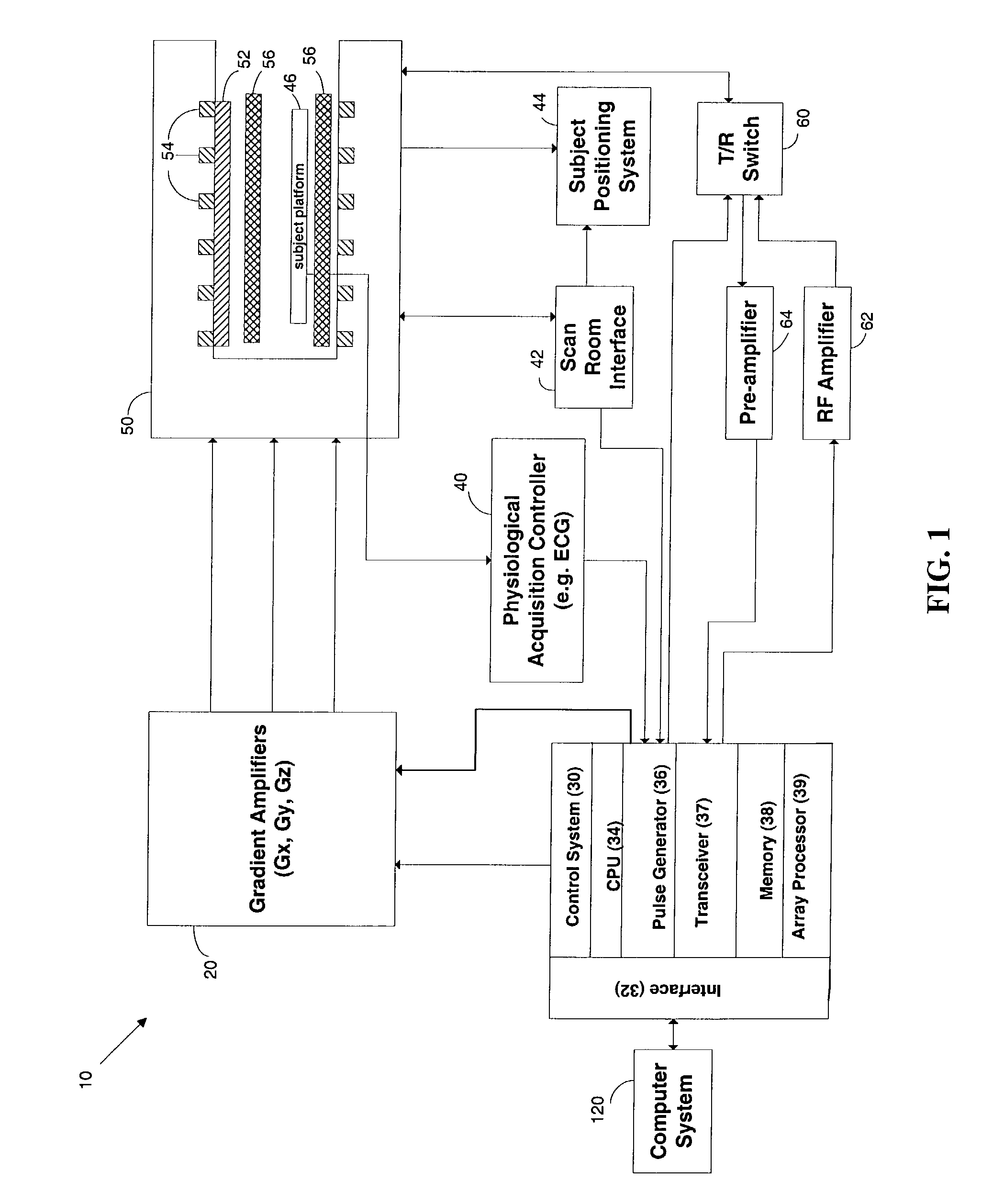
[0062]An exemplary MRI system is illustrated in FIG. 1. Referring to FIG. 1, the major components of a MRI system 10 that may be used to practice the disclosed methods are shown. The operation of the system is controlled by computer system 120 (see, Example 4 below). The computer system 120 includes a number of modules that communicate with each other, and with control system 30, through interface 32.

[0063]The control system 30 includes a set of modules connected together by an interface 32, and also connected to computer system 120 through interface 32. These modules include a CPU module 34. A pulse generator module 36 operates the system components to carry out the desired scan sequence and produces data which indicates the timing, strength and shape of the RF pulses produced, and the timing and length of the data acquisition window. The pulse generator module 36 connects to a set of gradient amplifiers 20, to indicate the timing and shape of the gradient pulses that are...

example 2

Cardiac Navigator

[0066]In this example, a cardiac navigator approach is described. The fast-flowing blood volume in the heart is tracked during the cardiac cycle. Due to its sensitivity to high velocity blood flow, the approach may be referred to as a Rapid-Motion-Perception (RaMP) navigator. In this approach, performing a complex difference analysis of the flow-sensitized profiles isolates the fast moving blood volume in the ventricles during the systolic emptying (or diastolic filling). The complex difference analysis suppresses the stationary or slow-moving spins in the excited volume. Simultaneous tracking of superior-inferior (SI) and anterior posterior (AP) movement of the heart is demonstrated by this approach. Small flip angle excitations gave sufficient SNR without creating saturation effects.

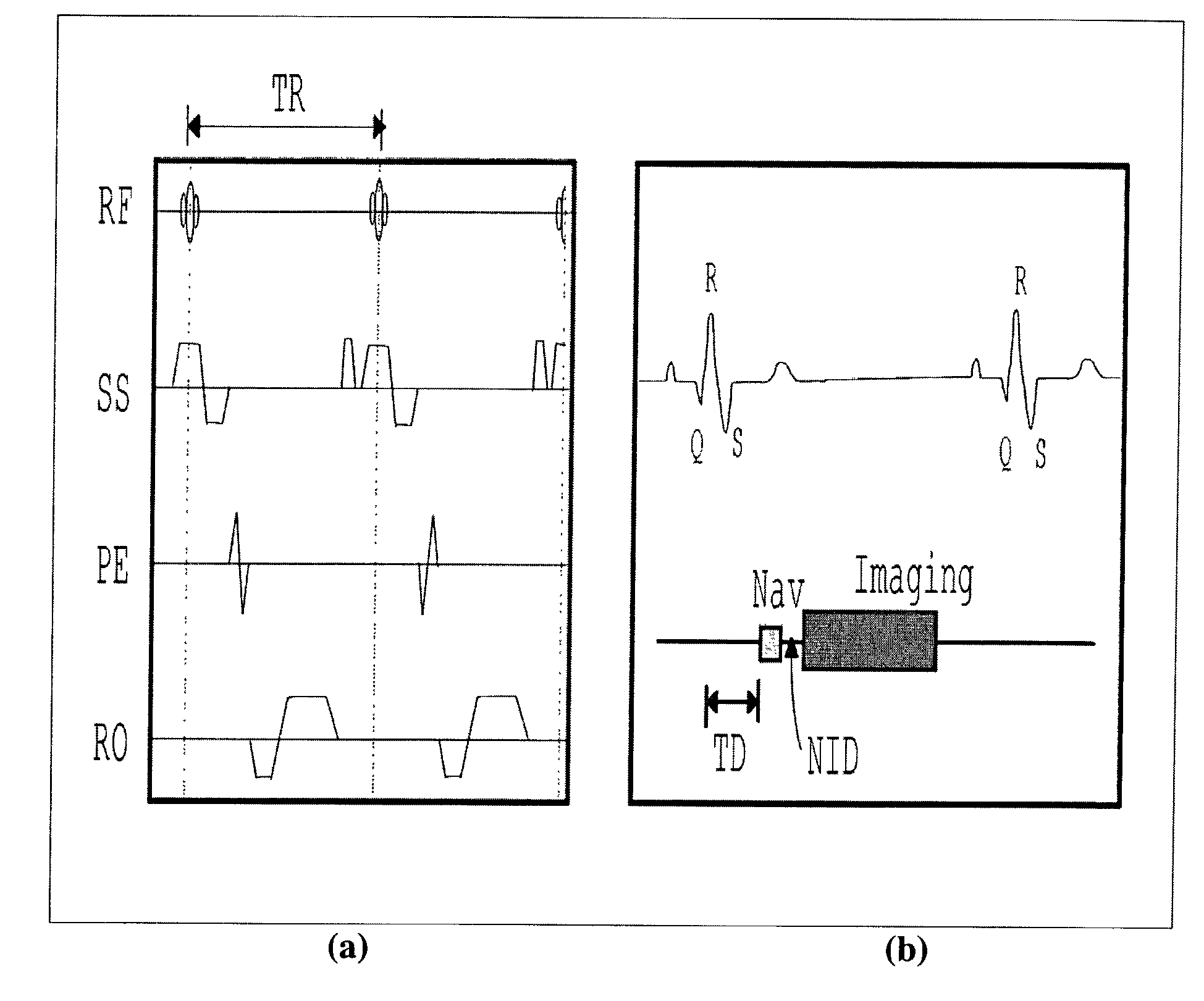
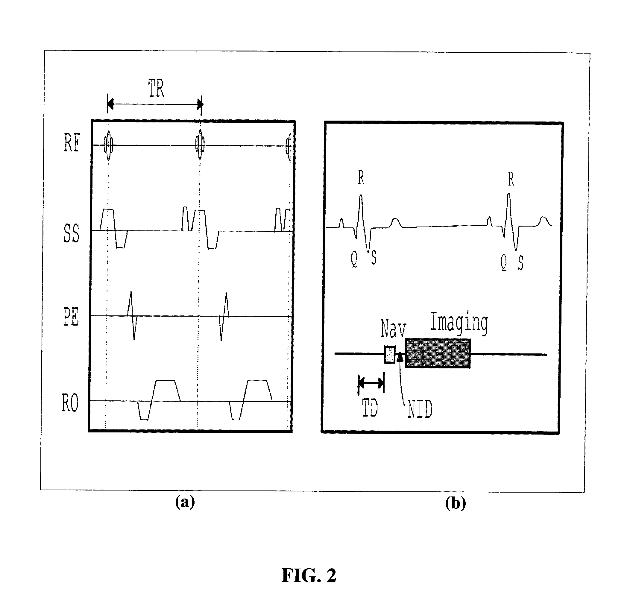
[0067]FIG. 2 shows a particular embodiment of the flow-sensitive navigator (RaMP) pulse scheme. In this instance, the RaMP sequence is comprised of a spoiled-Fast Low Angle Shot (FLASH...

example 3

Prospective Application of Navigator Signals

[0099]In this example, a prospective navigator approach was implemented on the clinical scanner described in Example 2 above earlier. FIGS. 16 and 18, respectively, show the RaMP implementation on two different human volunteers (Case I and Case II). These figures show the cardiac position over 15 successive cardiac cycles. Marker lines are drawn through the figures to illustrate the shift in position of the various organs, and the absence of heart motion.

[0100]In Case I (FIG. 16), an agarose-filled tube was placed above the phased-array surface coil, in order to track the motion correction determined from the RaMP implementation. The marker line drawn through the apex of the heart shows the motion of the tube and the various organs, and also shows that the heart appears stationary during the entire imaging cycle (15 heartbeats). The stationary nature of the heart image and the motion of the imaging slice can be tracked by monitoring the di...


PUM


Abstract

Navigator methods are disclosed that are based on detecting a flow-sensitive signal within a subject, and using the position of the signal to track subject motion between imaging sequences. In a disclosed embodiment, the fast-moving blood volume in the left ventricle of the heart is detected and used as a reference point to correct for cardiac motion that results from respiratory motion in a subject. The navigator based on the position of the fast-moving blood volume in the left ventricle may be applied prospectively to shift a subsequent imaging slice to compensate for subject motion, and thereby provide MRI images with increased clarity and resolution.

Description

FIELD[0001]The disclosure relates generally to magnetic resonance imaging (MRI). In particular, the disclosure relates to navigator methods for reducing MRI image artifacts that are due to subject motion, such as respiratory motion, during acquisition of a MR image.BACKGROUND[0002]During magnetic resonance image acquisition, subject motion can lead to artifacts, intensity loss, and lowered sharpness that degrade the clarity with which lesions and anatomic details can be depicted. For example, cardiac imaging sequences often span multiple heartbeats to obtain the necessary temporal and spatial resolutions. Under such conditions, motion artifacts due to respiratory motion can significantly impair the quality of the MR images (MRIs).[0003]A number of techniques have been proposed and developed over the years to minimize the effects of motion, particularly respiratory motion, on MR images. Breath-hold techniques and navigator methods are among these approaches. Each of these techniques ...

Claims


Application Information

Patent Timeline
Patent Type & Authority Patents(United States)
IPC IPC(8): A61B5/05
CPCA61B5/055A61B5/7207G01R33/5676G01R33/56316A61B5/721A61B5/7257G01R33/5613G01R33/56509G01R33/5673A61B5/7292
Inventor PAI, VINAY M.WEN, HAN
Owner UNITED STATES OF AMERICA
Why Eureka
Try Eureka