Space-time microwave imaging for cancer detection

a space-time microwave and cancer technology, applied in the field of medical imaging, can solve the problems of low ionizing radiation exposure, high false positive and false negative rate of x-ray mammography, and pain in breast compression, so as to reduce the number of false negatives, reliable detection, and the potential for sensitivity and resolution is sufficient.

Active Publication Date: 2009-08-04
WISCONSIN ALUMNI RES FOUND
View PDF29 Cites 47 Cited by
  • Summary
  • Abstract
  • Description
  • Claims
  • Application Information

AI Technical Summary

Benefits of technology

[0006]Space-time microwave imaging in accordance with the invention overcomes many of the limitations of conventional breast cancer screening modalities. Of particular significance, microwave imaging via space-time (MIST) beamforming has the potential to reduce the number of false negatives currently associated with conventional X-ray mammography. MIST exploits the significant dielectric-properties contrast between malignant and normal breast tissue at microwave frequencies by taking advantage of the exceptionally strong biophysical contrast mechanisms of clinical interest, such as water content, vascularization/angiogenesis, blood flow rate, and temperature. MIST techniques in accordance with the invention have the potential for sensitivity and resolution sufficient to allow reliable detection of extremely small (millimeter size) malignant tumors even in radiographically dense breast tissue or in the upper outer breast quadrant near the chest wall. In addition, MIST utilizes non-ionizing microwave radiation, is noninvasive, does not require the injection of contrast agents, and avoids the need for breast compression. The present invention also has the potential to reduce the number of false positives associated with conventional X-ray mammography and ther...

Problems solved by technology

However, X-ray mammography suffers from relatively high false positive and false negative rate...

Method used


Image

  • Space-time microwave imaging for cancer detection
  • Space-time microwave imaging for cancer detection
  • Space-time microwave imaging for cancer detection

Examples


Embodiment Construction

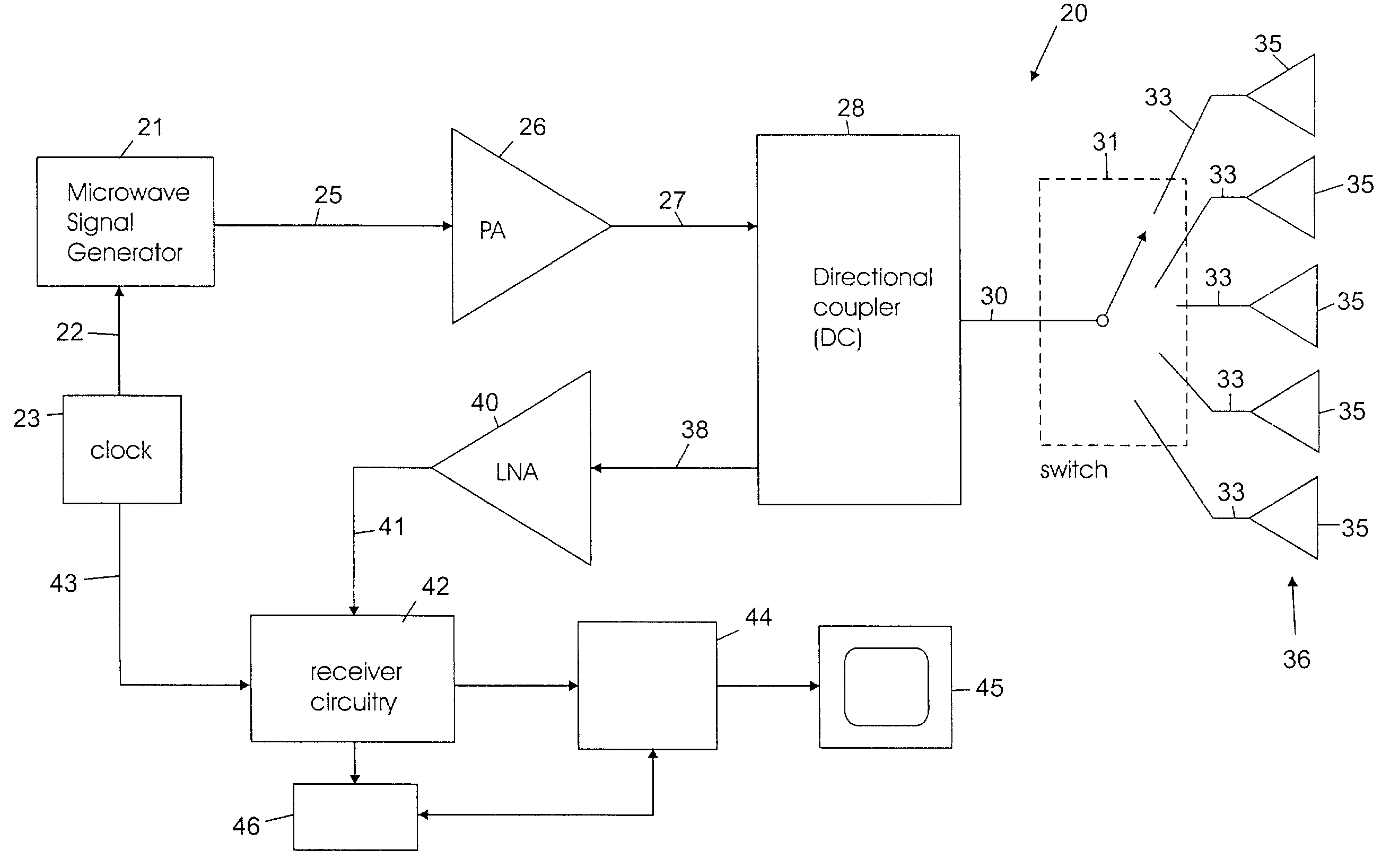
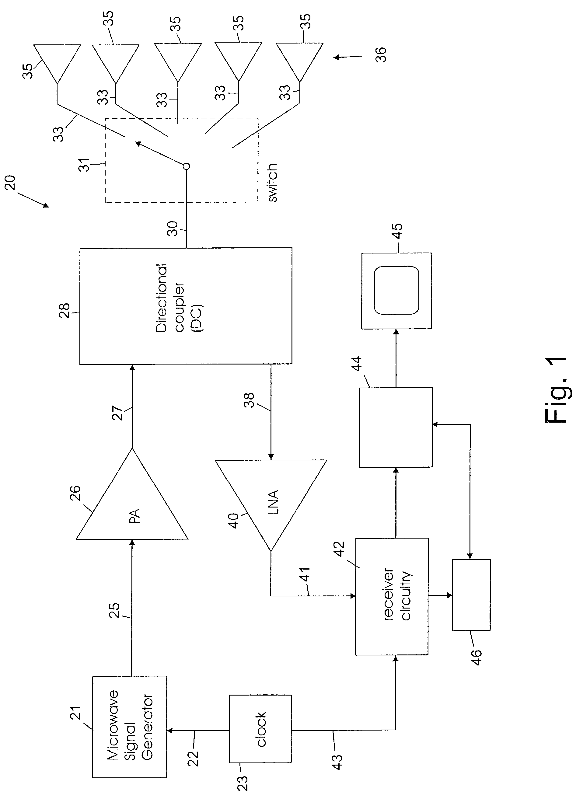
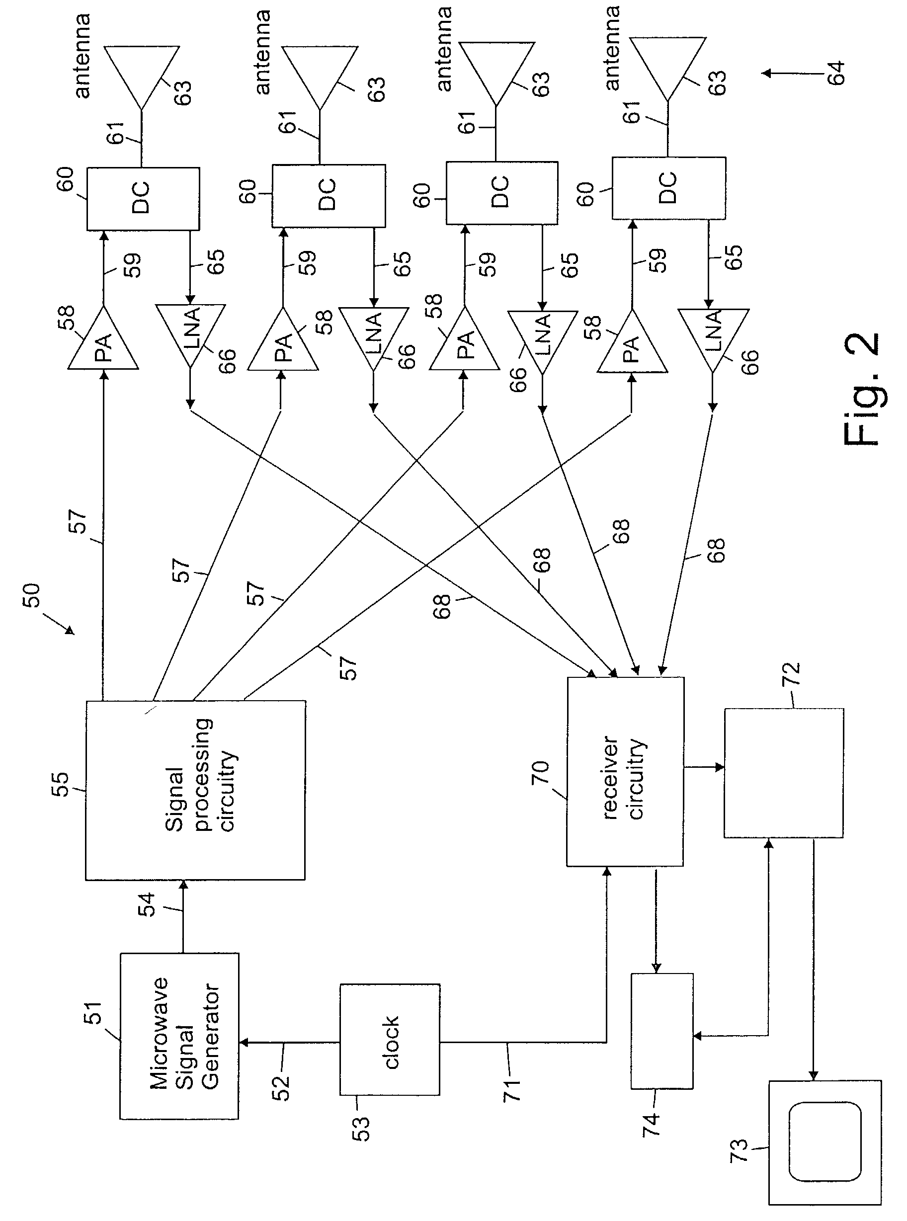
[0025]In one embodiment for carrying out space-time microwave imaging (MIST) in accordance with the invention, each antenna in an array of antennas sequentially transmits a low-power ultra-short microwave pulse into an object to be imaged, such as the breast, and collects the backscatter signal. The relative arrival times and amplitudes of backscattered signals received by the antennas across the antenna array provide information that can be used to detect the presence and determine the location of malignant lesions. Breast carcinomas act as significant microwave scatterers because of the large dielectric-properties contrast with the surrounding tissue. The problem of detecting and localizing scattering objects using pulsed signals and antenna arrays is similar to that encountered in radar systems, such as those used for air traffic control, military surveillance, and land-mine detection.

[0026]Data in published literature and from our measurements on freshly excised breast biopsy ti...


PUM


Abstract

Microwave imaging via space-time beamforming is carried out by transmitting microwave signals from multiple antenna locations into an individual to be examined and receiving the backscattered microwave signals at multiple antenna locations to provide received signals from the antennas. The received signals are processed in a computer to remove the skin interface reflection component of the signal at each antenna to provide corrected signal data. The corrected signal data is provided to a beamformer process that time shifts the received signals to align the returns from a scatterer at a candidate location, and then passes the time aligned signals through a bank of filters, the outputs of which are summed, time-gated and the power therein calculated to produce the beamformer output signal at a candidate location. The beamformer is then scanned to a plurality of different locations in the individual by changing the time shifts, filter weights and time-gating of the beamformer process. The output power may be displayed as a function of scan location, with regions of large output power corresponding to significant microwave scatterers such as malignant lesions.

Description

CROSS-REFERENCE TO RELATED APPLICATION[0001]This application claims the benefit of provisional application No. 60 / 303,461, filed Jul. 6, 2001, the disclosure of which is incorporated herein by reference.REFERENCE TO GOVERNMENT RIGHTS[0002]This invention was made with United States government support awarded by the following agencies: NSF 9900280. The United States government has certain rights in this invention.FIELD OF THE INVENTION[0003]The present invention pertains generally to the field of medical imaging and particularly to microwave imaging of tissue for the detection and location of tumors.BACKGROUND OF THE INVENTION[0004]Various imaging techniques have been employed for detecting and locating cancerous tumors in body tissue. X-ray and ultrasound imaging techniques are commonly utilized in screening for breast cancer. X-ray mammography is the most effective current method for detecting early stage breast cancer. However, X-ray mammography suffers from relatively high false p...

Claims


Application Information

Patent Timeline
IPC IPC(8): G01R27/32A61B5/05
CPCA61B5/05A61B5/0507A61B5/7257A61B18/1815
Inventor VAN VEEN, BARRY D.HAGNESS, SUSAN C.BOND, ESSEX JULIANLI, XU
Owner WISCONSIN ALUMNI RES FOUND
Why Eureka
Try Eureka