Method of designing a shim coil to reduce field settling time

a shim coil and field settling technology, applied in the field of mr systems, can solve the problems of affecting data acquisition and reconstruction of an mr image, affecting the accuracy of center magnetic field that is significantly out of range, and undesirable field settling effect, so as to reduce the flux leakage and the effect of impacting the field settling tim

Active Publication Date: 2009-08-04
GENERAL ELECTRIC CO
View PDF34 Cites 11 Cited by
  • Summary
  • Abstract
  • Description
  • Claims
  • Application Information

AI Technical Summary

Benefits of technology

[0009]The present invention provides a shim coil for the magnet assembly of an MR scanner that overcomes the aforementioned drawbacks. The shim coil is constructed to have an appropriate shim coil geometry, e.g., number of turns, and an appropriate shim coil position that results in both a desired field homogeneity and a desired B0 field settling time. In this regard, the impact on field settling time is considered when designing and constructing the shim coil. Moreover, this simultaneous satisfaction of both field homogeneity and field settling time is achieved without a reduction of flux leakage from the shim coil, modification of main magnet protection circuitry, and without necessarily decoupling the shim coil from the overall main magnet.
[0011]In accordance with another aspect of the invention, the invention is embodied in a computer program stored on a computer readable storage medium and having instructions which, when executed by a computer, cause the computer to model time dependence of a B0 field generated by a magnet assembly as B0(t)=A0+A1e−t / τ<sub2>1< / sub2>+A2e−t / τ<sub2>2< / sub2>+ . . . +Ane−t / τ<sub2>n< / sub2>, where A0 is a settled value of the B0 field, τi is the ith settling time constant, 1≦i≦n, and Ai is the amplitude of the ith exponential settling term. The computer is further caused to identify settling terms, Aie−t / τ<sub2>i< / sub2>, having similar time constants, τ, and determine amplitudes, Ai, of the identified settling terms that will result in those amplitudes being balanced to reduce B0 field settling time of the magnet assembly. Alternately, the computer may determine the amplitudes that will result in a reduction in the time constants.
[0012]According to another aspect, the present invention is embodied in a magnetic resonance (MR) scanner. The scanner includes a magnet designed to impress a polarizing magnet field. The magnet has a main superconducting coil designed to generate a B0 field and a superconducting shim coil inductively coupled to the main superconducting coil to improve homogeneity of the B0 field. The magnet also has an RT shim coil, inductively coupled to both the main superconducting coil and the superconducting shim coil, to improve homogeneity of the B0 field. The position and the geometry of the RT shim coil are selected such that the B0 field has both a desired homogeneity and a desired field settling time.

Problems solved by technology

As a result of the magnet manufacturing process, it is not uncommon for the magnet to produce a very inhomogeneous field ranging from several hundred parts per million (ppm) to several thousand ppm, and a non-accurate center magnetic field that is significantly out of range.
As is widely known, these variations negatively affect data acquisition and reconstruction of an MR image.
The current flow subsequently decays from the resistors, resulting in an undesirable field settling effect.
This settling time necessarily increases scan time and negatively affects throughput.

Method used


Image

  • Method of designing a shim coil to reduce field settling time
  • Method of designing a shim coil to reduce field settling time
  • Method of designing a shim coil to reduce field settling time

Examples


Embodiment Construction

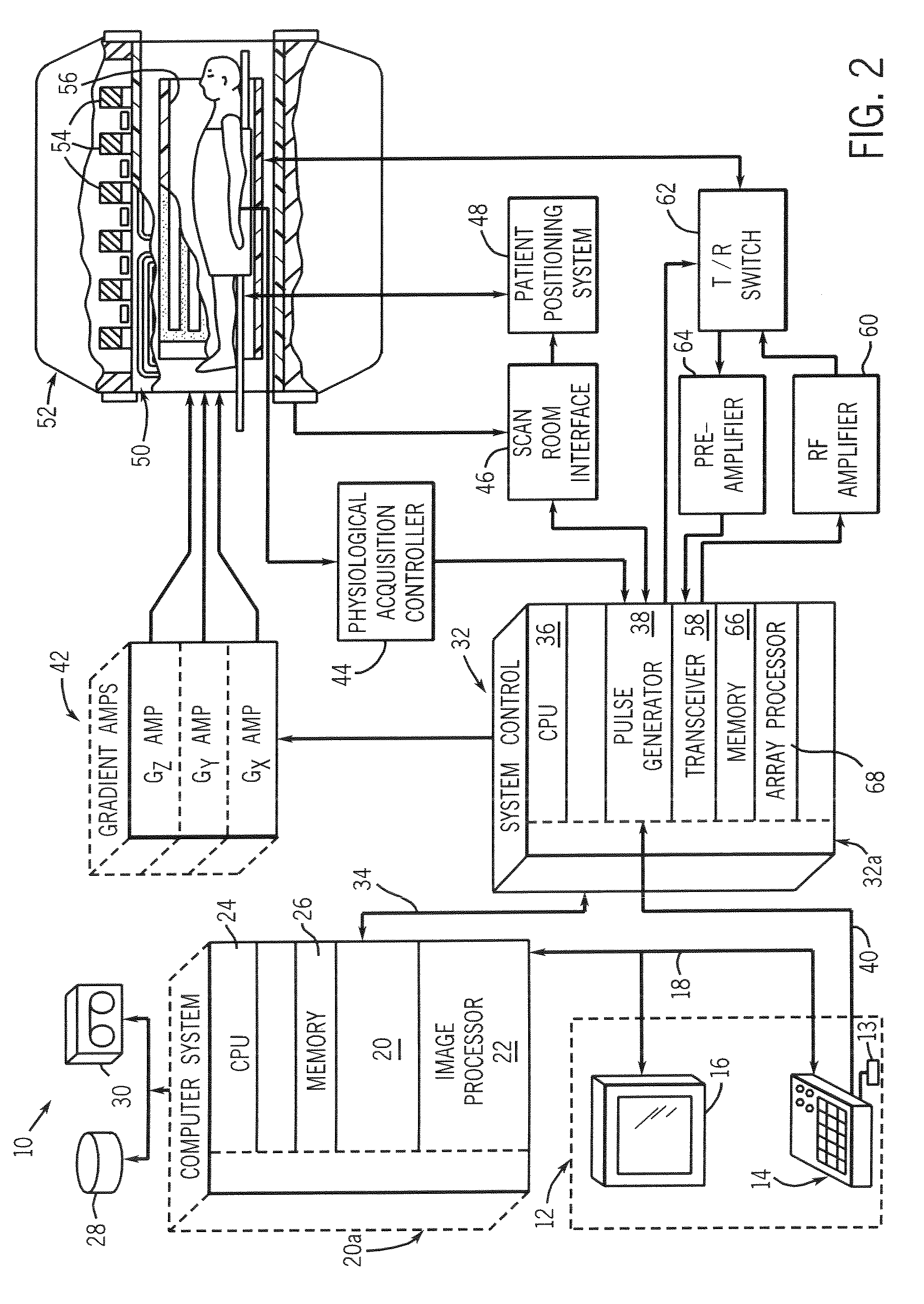
[0021]Referring to FIG. 2, the major components of a preferred magnetic resonance imaging (MRI) system 10 incorporating the present invention are shown. The operation of the system is controlled from an operator console 12 which includes a keyboard or other input device 13, a control panel 14, and a display screen 16. The console 12 communicates through a link 18 with a separate computer system 20 that enables an operator to control the production and display of images on the display screen 16. The computer system 20 includes a number of modules which communicate with each other through a backplane 20a. These include an image processor module 22, a CPU module 24 and a memory module 26, known in the art as a frame buffer for storing image data arrays. The computer system 20 is linked to disk storage 28 and tape drive 30 for storage of image data and programs, and communicates with a separate system control 32 through a high speed serial link 34. The input device 13 can include a mous...


PUM

PropertyMeasurementUnit
settling timeaaaaaaaaaa
timeaaaaaaaaaa
settling timeaaaaaaaaaa

Abstract

A shim coil design technique determines a position and a geometry of a room temperature (RT) shim coil to provide both a desired field homogeneity and a desired B0 field setting time. The simultaneous satisfaction of both field homogeneity and field settling time is achieved without a reduction of flux leakage from the shim coil, modification of main magnet protection circuitry, and without necessarily decoupling of the shim coil from the overall main magnet.

Description

BACKGROUND OF THE INVENTION[0001]The present invention relates generally to MR systems and, more particularly, to a shim coil of a magnet assembly of an MR system that achieves a near-homogeneous magnetic field with reduced B0 field settling time.[0002]It is generally known that when a substance such as human tissue is subjected to a uniform magnetic field (polarizing field B0), the individual magnetic moments of the spins in the tissue attempt to align with this polarizing field, but precess about it in random order at their characteristic Larmor frequency. If the substance, or tissue, is subjected to a magnetic field (excitation field B1) which is in the x-y plane and which is near the Larmor frequency, the net aligned moment, or “longitudinal magnetization”, MZ, may be rotated, or “tipped”, into the x-y plane to produce a net transverse magnetic moment Mt. A signal is emitted by the excited spins after the excitation signal B1 is terminated and this signal may be received and pro...

Claims


Application Information

Patent Timeline
Patent Type & Authority Patents(United States)
IPC IPC(8): H01F7/00H01F1/00H01F6/00
CPCG01R33/3875
Inventor HOLLIS, TIMOTHY J.HAVENS, TIMOTHY J.DUBY, TOMAS
Owner GENERAL ELECTRIC CO
Why Eureka
Try Eureka