Spectrophotometric method and apparatus

a spectrophotometric and apparatus technology, applied in the field of spectrophotometric methods, can solve the problems inability to use, and a lot of time and effort in cleaning after measurement, so as to avoid the risk of deterioration in accuracy

Inactive Publication Date: 2009-08-18
SHIMADZU CORP
View PDF5 Cites 20 Cited by
  • Summary
  • Abstract
  • Description
  • Claims
  • Application Information

AI Technical Summary

Benefits of technology

[0009]In view of the above problems, it is a primary object of the present invention to provide a spectrophotometric method and apparatus capable of performing a transmission measurement of a sample solution with a small volume of about 1 to 2 μL or less in a simplified structure and in a user-friendly manner.
[0013]As above, the above spectrophotometric method and apparatus of the present invention can analyze a sample solution with an extremely small volume of the order capable of being held in the sample-holding hole based on a surface tension. That is, a required volume of sample solution may be only about 1 to 2 μL or less. This shows suitability for analyses of a sample solution with a small volume, such as a biological sample. In addition, a sample solution can be set up only by dropping the sample solution into the sample-holding hole. Thus, operations for analysis can be performed in a drastically simplified manner without a time-consuming operation. Further, the sample solution has a contact with only the sample-holding hole and its surrounding of the sampler, and the sample-holding hole has the upper and lower openings. This makes it possible to readily perform a cleaning operation for completely removing the sample solution attached on the sampler. Furthermore, the sampler itself can be formed at an extremely low cost to reduce an analytic cost even if the sampler is used in a disposable manner. The sample solution has no contact with a body of the apparatus. Thus, the costly apparatus body can be kept from being damaged and contaminated so as to avoid an increase in burden of maintenance / inspection.
[0014]In the spectrophotometric method and apparatus of the present invention, the sampler may be formed in various shapes. In one preferred embodiment, the sample-holding hole of the sampler is formed in a truncated conical shape. While even a sample-holding hole formed, for example, in a truncated horn shape, can maintain the function of holding a sample solution based on a surface tension, corners residing inside the sample-holding hole are liable to cause residua of the sample solution therein. In contrast, the sample-holding hole having a truncated conical shape can eliminate such corners to facilitate a cleaning operation.
[0016]As a specific example of the correction means, in the case where water is used as a solvent in the sample solution, the correction may be performed by monitoring an absorbed amount of near-infrared light subject to optical absorption by water, calculating a coefficient for correcting a variation in light path length, based on the monitored absorbed amount, and multiplying an intensity of received near-infrared light by the calculated coefficient. The correction means makes it possible to eliminate or reduce an error due to fluctuation in volume of a sample solution dropped into the sample-holding hole of the sampler so as to achieve enhanced analytic accuracy and reproducibility.
[0018]This configuration makes it possible to detect light having a given wavelength range approximately simultaneously without the need for sequentially scanning wavelengths of a monochromatic light picked up from a spectroscope as in a so-called sequential spectrophotometer. Thus, the measurement can be completed within a short time to avoid the risk of deterioration in accuracy due to the aforementioned vaporization of the solvent.

Problems solved by technology

Particularly, in analyses of DNA, some analyses have to be conducted using only several μL or less of sample solution, due to scarcity and costliness of a sample.
Heretofore, there has been known a vessel suitable for spectrophotometrically measuring such a small volume of sample solution [see, for example, Japanese Patent Laid-Open Publication No. 05-302893 [Patent Publication 1)], because the above cuvette cell cannot be used for the purpose of analyzing a small volume of sample solution.
Generally, the capillary cell still requires preparing several μL or more of sample solution at minimum, and cannot be used for any analysis of a sample solution with a volume of less than the lower limit.
The capillary cell has another problem about the needs for filling the cell with a sample solution in a complicated manner and taking a lot of time and effort in cleaning after measurement.
While it is desirable to clean the end faces using water or organic solvent because the wiping operation using a laboratory wipe is not sufficient to completely eliminate an influence of a previously-measured sample solution, such a cleaning operation is fairly bothersome.
Moreover, this operation has to be performed for each sample measurement, or it is impossible to measure a number of samples while automatically replacing one with another.
This analytic operation cannot be the to be efficient.
Furthermore, the device designed to partly have a direct contact with a sample solution is likely to cause damages and contamination in the contact portions, and, in that event, an analytic performance will be deteriorated.

Method used


Image

  • Spectrophotometric method and apparatus
  • Spectrophotometric method and apparatus
  • Spectrophotometric method and apparatus

Examples


Embodiment Construction

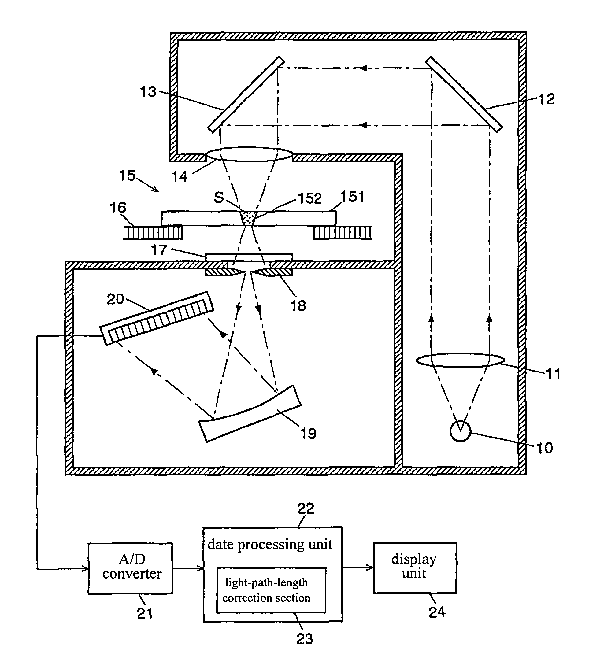
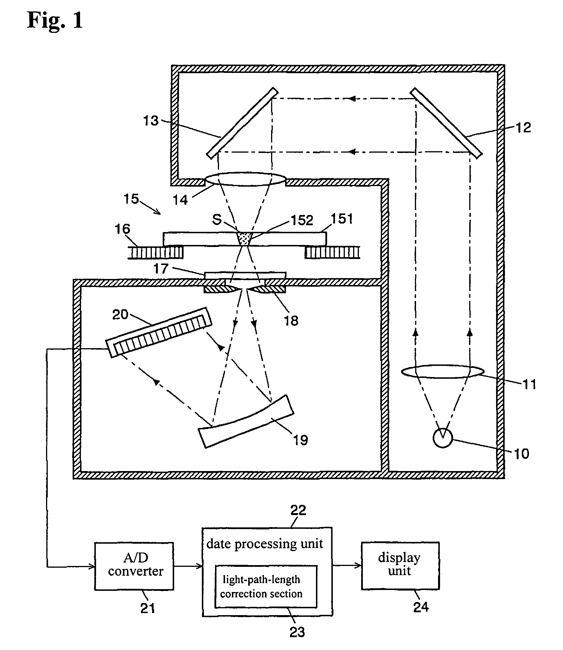
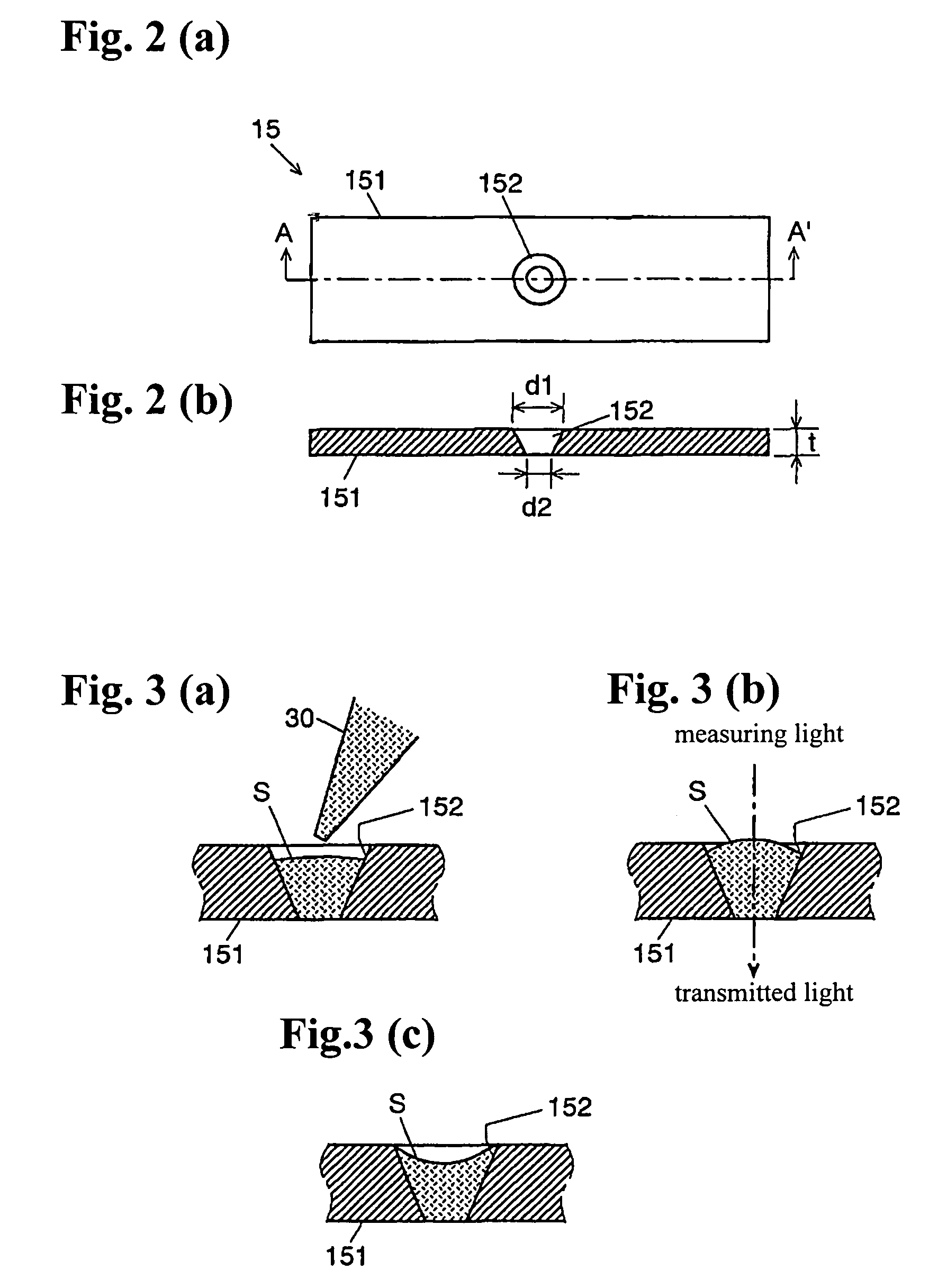
[0030]With reference to the drawings, an ultraviolet-visible spectrophotometric apparatus according to one embodiment of the present invention, which implements a spectrophotometric method according to one embodiment of the present invention, will now be described. FIG. 1 is a schematic block diagram showing the ultraviolet-visible spectrophotometric apparatus according to this embodiment. FIG. 2(a) is a top plan view showing a sampler 15 for use with the ultraviolet-visible spectrophotometric apparatus, and FIG. 2(b) is a sectional view taken along the line A-A′ in FIG. 2(a). FIGS. 3(a) to 3(c) are explanatory schematic diagrams of an analytic procedure.

[0031]In FIG. 1, light emitted from a light source 10 is collimated into a parallel light by a lens 11, and them reflected by a reflecting mirror 12 and a reflecting mirror 13 in this order. Then, the reflected light is focused by a lens 14, and emitted as a measurement light to a sample to be analyzed, or a target sample, from appr...


PUM


Abstract

Disclosed is a spectrophotometry for a spectral transmission measurement of an extremely small volume of sample solution. A sampler 15 is formed of a flat plate member formed with a sample-holding hole 152 which penetrates the flat plate member in its thickness direction and has a reverse truncated cone shape, and a target sample solution is dropped into the sample-holding hole 152 of the sampler 15 positioned approximately horizontally and held in the hole 152 based on a surface tension of the sample solution in the form of a droplet S. Then, a measurement light is emitted to the held droplet S from directly above. A transmitted light getting out of the droplet S downward is introduced to a diffraction grating 19 through a window plate 17 and a slit 18, and dispersed in a wavelength dependent manner. The resulting light with dispersed wavelength components is detected by a multichannel detector 20 approximately simultaneously.

Description

BACKGROUND OF THE INVENTION[0001]1. Field of the Invention[0002]The present invention relates to a spectrophotometric method of irradiating a sample solution with light to measure a transmitted light therefrom, and a spectrophotometric apparatus for use in the spectrophotometric method. More specifically, the present invention relates to a spectrophotometric method and apparatus suitable for spectrophotometrically measuring a small volume of sample solution.[0003]2. Description of the Background Art[0004]In a process for measuring a transmittance or absorbance of a sample solution using a spectrophotometer, such as an ultraviolet-visible spectrophotometer, a rectangular or cylindrical cuvette cell is generally used for containing the sample solution. A typical cuvette cell has an inner volume of several mL or more, and it is required to prepare a sample solution in a sufficient volume to fill the cuvette cell.[0005]Recent years, an ultraviolet-visible spectrophotometer has been incr...

Claims


Application Information

Patent Timeline
Patent Type & Authority Patents(United States)
IPC IPC(8): G01J3/28
CPCG01J3/02G01J3/0291G01N21/31G01N21/03G01N2021/0346G01N2021/035
Inventor TSUKUDA, YASUO
Owner SHIMADZU CORP
Why Eureka
Try Eureka