Devices for continuous sampling of airborne particles using a regenerative surface

a technology of regenerative surface and airborne particles, which is applied in the direction of fluid speed measurement, electric signalling details, feed/discharge of settling tanks, etc., can solve the problems of reducing the accuracy of measurement of total particulate mass concentration and size-fractionation, and affecting the collection efficiency of airborne particles. , to achieve the effect of convenient cleaning and improved collection efficiency

Inactive Publication Date: 2009-08-25
FLIR DETECTION
View PDF79 Cites 42 Cited by
  • Summary
  • Abstract
  • Description
  • Claims
  • Application Information

AI Technical Summary

Benefits of technology

[0025]In another embodiment, the material of the collection surface is selected because of its porous nature. The pore sizes are sufficiently large to allow the fluid in which the particulates are entrained to freely pass through the archival surface, yet sufficiently small to prevent the particulates themselves from passing through the archival surface. Thus, the particulates are “filtered” from the fluid stream by the collection surface. To enhance removal of the particles, a fluid back flush can be employed. If the container is under a partial vacuum, the back flushed particles will be drawn into the container. Note that if the fluid is a gas, the concern regarding the use of so much liquid so as to undesirably dilute the sample of particles is obviated. In one embodiment, a vacuum is placed in fluid communication with an opposing side of a porous collection surface, causing the particles to adhere to the collection surface. When the vacuum source is no longer in fluid communication with the collection surface, the particles are readily removed.
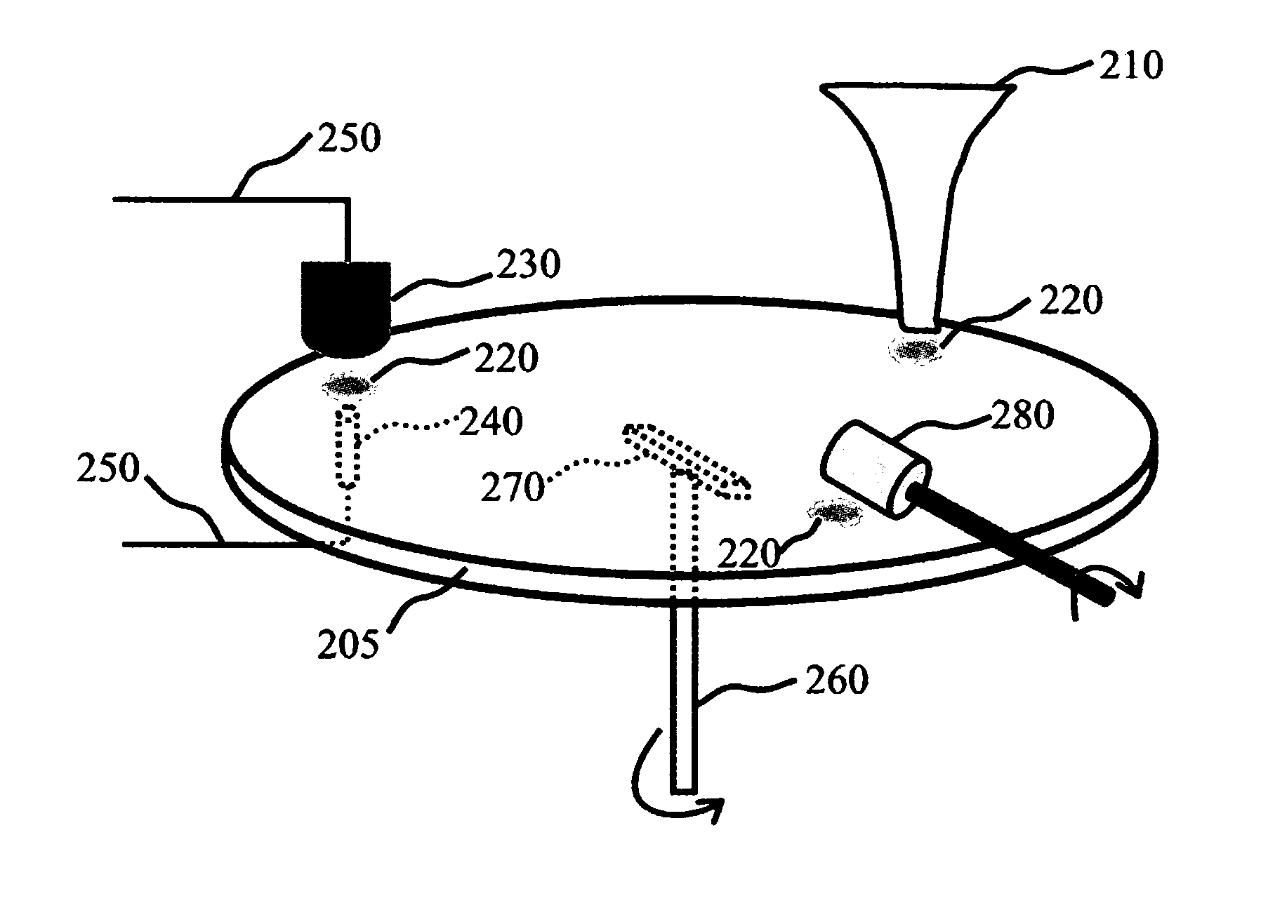
[0035]One component of the invented devices is an impaction plate. One of its features is a collection surface, on which a spot of airborne particles gets collected when the devices are in operation. In some embodiments, the collection surface is smooth, and is therefore easily cleaned by a surface regenerator. In other embodiments, the collection surface comprises features that improve the collection efficiency of impacting airborne particles, such as pyramid-shaped structures of about 1-10 μm in height and width. In some embodiments, the impaction plate comprises more than one, i.e. a plurality of collection surfaces.
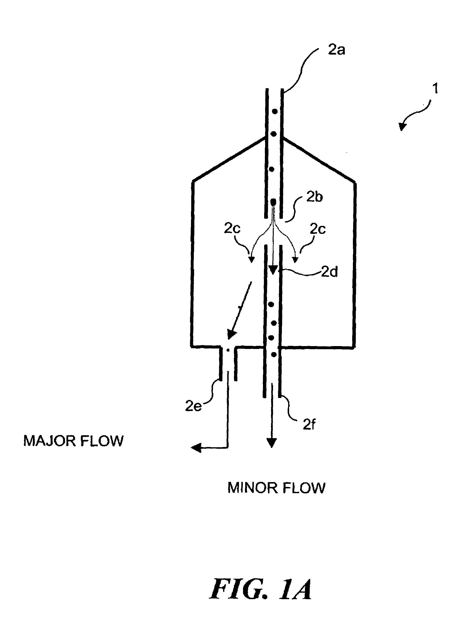
[0036]Another component of the invented devices is a spotting nozzle. The spotting nozzle directs an air stream towards the collection surface of the impaction plate. The resulting impact of the air stream produces a spot that contains airborne particles on the collection surface. In some embodiments a particle concentrator, such as a virtual impactor, is placed upstream of the spotting nozzle, which increases the concentration of airborne particles within a desirable size range. In some embodiments, a size selective inlet is placed upstream of the spotting nozzle, which eliminates airborne particles greater than a desirable size. In some embodiments, both a concentrator and a size selective inlet are present upstream of the spotting nozzle. In some embodiments the spotting nozzle is substantially vertical while the collection surface is substantially horizontal. In preferred embodiments the nozzle, impaction surface and air stream velocity are configured so that the spot is enriched in particles of about 0.5-10 μm sizes.
[0040]Another component present in some embodiments is a liquid coating applicator. It moistens the collection surface prior to impaction of the airstream, and thus helps trapping airborne particles and enhances the collection efficiency. The liquid coating applicator may be, for example, a felt tip pen. It might alternatively be similar to inkjet printing devices. It comprises a reservoir of liquid to be applied to the collection surface. There are several types of liquids that may be used, including alcohol, glycerol, or a medium weight hydrocarbon such as octane.

Problems solved by technology

However, a significant disadvantage of such an impactor is the deposition of particulates on surfaces of the impactor other than the intended collection surfaces.
This phenomenon reduces the accuracy of measurement of total particulate mass concentration and of the size-fractionation of particulates, since such losses cannot be accurately estimated for aerosols or particulates of varying size, shape, or chemistry.
Still, particulate “wall loss,” i.e., unintended deposition of particulates on various surfaces of virtual impactor structures, especially at curved or bent portions, remains a challenge with some designs of virtual impactors, because typically, many stages or layers of virtual impactors are required to complete particulate separation.
While archival samples prepared by such a method are useful, the manual nature of such a method is time consuming and costly.
Furthermore, during each step in which a sample is handled or manipulated (collection, separation, storage, and analysis), there is a significant chance that the sample will be inadvertently contaminated.
If the archival sample is merely a single sample collected over a 24-hour period, rather than 24 samples collected each hour for 24 hours, then little information can be obtained about when the excess emissions actually occurred, making it more difficult to determine the cause of the excess emissions.
Regardless of how effective impact collectors are at removing particulates from a fluid stream (such as air), the collected particulates generally cannot readily be analyzed while remaining deposited on the impact collection surface.
The typical problem facing the aerosol field is that of collecting and characterizing airborne particles.
While autofluorescent properties may be useful in detecting biological particles, their in situ measurement is challenging for a number of reasons.
It is particularly difficult to measure fluorescent characteristics of minuscule particles in an airborne state.
The particles are available for analysis quite briefly, thus making it difficult to determine several informative characteristics.
In addition, the equipment required comprises expensive powerful lasers and sensitive fluorescence photodetectors or photon counters.
The resulting devices are large and expensive, making this technology unlikely to be adopted for some applications, such as routine monitoring of civilian buildings.
Continuous use of consumables and / or labor can become problematical and prohibitively expensive.
Therefore, monitoring systems based on extractive techniques are also of questionable value for routine, continuous use.

Method used


Image

  • Devices for continuous sampling of airborne particles using a regenerative surface
  • Devices for continuous sampling of airborne particles using a regenerative surface
  • Devices for continuous sampling of airborne particles using a regenerative surface

Examples


example

Detection of Aerosolized Fluorescent Particles Using a Regenerative Surface

[0356]A regenerative surface air sampler based was constructed. The impaction plate was made of aluminum, and was shaped as a lobed cam with three regenerative surfaces. Components of the system included an inertial impactor, a fluorescence detector, and a felt wheel brush surface regenerator. The fluorescence detector was arranged essentially as depicted in FIG. 28, with transmission characteristics of the dichroic mirror, excitation and emission filters as shown in FIG. 30. The UV LED emission was specified to be about 375+ / −3 nm.

[0357]Biological aerosol was simulated with a fluorescent powder (UVPN UV Powder sold by LDP, LLC (www.maxmax.com)). It was aerosolized by tapping an open envelope of the powder three times, releasing approximately 100 milligrams of the powder into the air several feet away from the air inlet to the sensor.

[0358]Results of the test are shown in FIG. 31. As can be seen, the apparatu...


PUM

PropertyMeasurementUnit
sizeaaaaaaaaaa
heightaaaaaaaaaa
sizeaaaaaaaaaa

Abstract

Airborne particles are impacted on a collection surface, analyzed, and then the collection surface is regenerated. Thus, the same collection surface can be used in numerous cycles. The analysis can be focused on one or more properties of interest, such as the concentration of airborne biologicals. Sensors based on regenerative collection surfaces may be incorporated in many networks for applications such as building automation.

Description

RELATED APPLICATIONS[0001]This application is a continuation in part of a prior application Ser. No. 10 / 366,595, filed Feb. 11, 2003 now U.S. Pat. No. 6,938,777, which is based on a prior provisional application Ser. No. 60 / 355,915, filed on Feb. 11, 2002, and is further a continuation in part of a prior application Ser. No. 09 / 955,481, filed on Sep. 17, 2001 now U.S. Pat. No. 6,695,146, which is a continuation-in-part of prior utility application Ser. No. 09 / 265,620, filed on Mar. 10, 1999 now U.S. Pat. No. 6,363,800, and is further a continuation-in-part of a utility application Ser. No. 09 / 494,962, filed on Jan. 31, 2000 now U.S. Pat. No. 6,290,065, which is a continuation-in-part of application Ser. No. 09 / 191,980 now U.S. Pat. No. 6,062,392, filed on Nov. 13, 1998 the benefits of the filing dates of which are hereby claimed under 35 U.S.C. §119(e) and 35 U.S.C. §120.FIELD OF INVENTION[0002]The invention relates to methods and devices for continuous monitoring of airborne partic...

Claims


Application Information

Patent Timeline
Patent Type & Authority Patents(United States)
IPC IPC(8): G01N7/02B01D21/24B01D45/08B81B1/00G01N1/02G01N1/22G01N1/28G01N1/34G01N1/40G01N15/00G01N15/02G01N15/06G01N35/00
CPCB01D21/2455B01D45/08G01N1/2208G01N1/2273G01N15/0255G01N15/0637G01N2015/0288G01N35/00009G01N2001/022G01N2015/0026G01N2015/0046G01N2015/0088
Inventor CALL, CHARLES JOHNMERRILL, EZRABECKIUS, ROBERT
Owner FLIR DETECTION
Why Eureka
Try Eureka