
Inkjet printhead with low voltage ink vaporizing heaters

a heater and inkjet technology, applied in printing, inking apparatus, other printing apparatus, etc., can solve the problems of oxidation of most heater materials, large drive transistors for high voltage drive pulses, and high corrosion of heater elements, so as to improve the efficiency of the drop ejection process and reduce the drive voltage. , the effect of reducing the drive curren

Inactive Publication Date: 2009-09-01
MEMJET TECH LTD +1
View PDF36 Cites 25 Cited by
  • Summary
  • Abstract
  • Description
  • Claims
  • Application Information

AI Technical Summary

Benefits of technology

[0015]The invention is predicated on reducing the drive voltage while improving the efficiency of the drop ejection process such that the drive current remains manageably low. With the realization that high drive pulse voltage is not a fixed parameter of printhead design, the benefits of low voltage printhead operation can be incorporated into a design that yields efficiencies that negate the circumstances that created the initial demand for high voltage operation. The low voltage operation of the heater elements is more compatible with the high density CMOS (complimentary metal-oxide semiconductor) devices used in the printhead. The drive transistors for each nozzle can be significantly smaller and this in turn improves the nozzle density. A lower voltage drive pulse allows the heater to directly contact the ink without electrolytic breakdown. Having both the drive transistors for the heater elements and the rest of the CMOS devices in the drive circuitry operate at relatively low voltages simplifies the power supply to the printhead as a whole. This allows a more compact printhead design and has significant fabrication cost advantages.

Problems solved by technology

High temperatures and frequently vaporizing ink (typically water based) will quickly oxidate most heater materials.
The severe hydraulic forces from the cavitation of collapsing bubbles is also highly corrosive to the heater elements.
Unfortunately, high voltage drive pulses require larger drive transistors.
High voltages also create the potential for arcing and other breakdown mechanisms.
For example, the heater must be electrically insulated from the ink because a high voltage causes electrolytic breakdown of the materials in the ink and chamber.
The voltages can be reduced and the current increased to give a pulse of the same power, but high currents induce electromigration above a certain threshold (electromigration is an atomic migration away from points if high current density that eventually thins and ultimately fractures the heater element), higher parasitic resistances (in the heater contacts etc), the drive transistor operates less efficiently and the ‘ground bounce’ is more severe.

Method used


Image

  • Inkjet printhead with low voltage ink vaporizing heaters
  • Inkjet printhead with low voltage ink vaporizing heaters
  • Inkjet printhead with low voltage ink vaporizing heaters

Examples


Embodiment Construction

[0091]In the description than follows, corresponding reference numerals, or corresponding prefixes of reference numerals (i.e. the parts of the reference numerals appearing before a point mark) which are used in different figures relate to corresponding parts. Where there are corresponding prefixes and differing suffixes to the reference numerals, these indicate different specific embodiments of corresponding parts.

Overview of the Invention and General Discussion of Operation

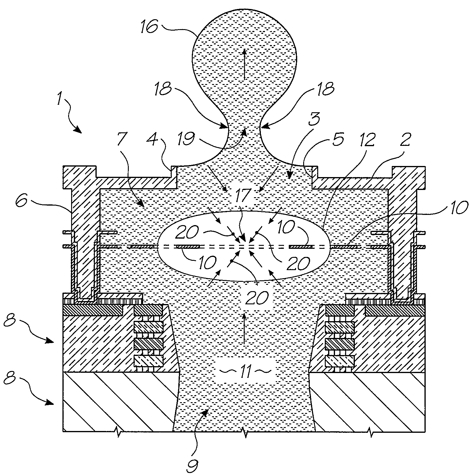
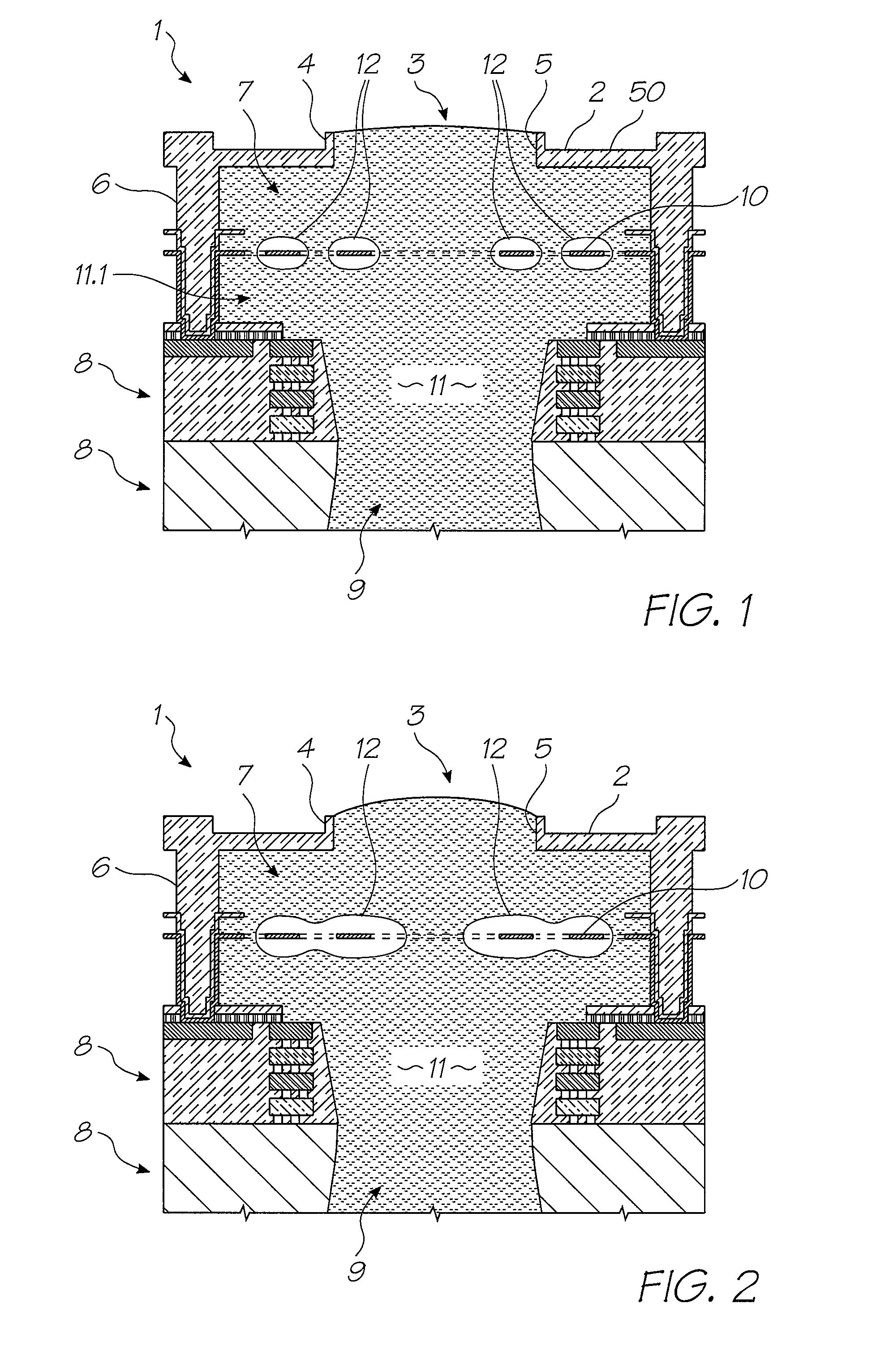
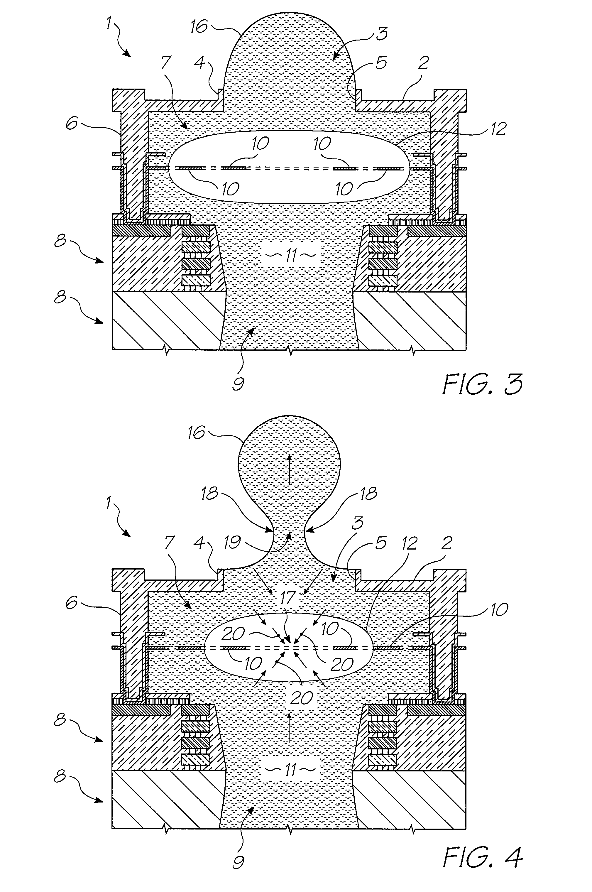
[0092]With reference to FIGS. 1 to 4, the unit cell 1 of a printhead according to an embodiment of the invention comprises a nozzle plate 2 with nozzles 3 therein, the nozzles having nozzle rims 4, and apertures 5 extending through the nozzle plate. The nozzle plate 2 is plasma etched from a silicon nitride structure which is deposited, by way of chemical vapor deposition (CVD), over a sacrificial material which is subsequently etched.

[0093]The printhead also includes, with respect to each nozzle 3, side walls 6...


PUM


Abstract

There is disclosed an ink jet printhead which comprises a plurality of nozzles and one or more heater elements 10 corresponding to each nozzle. Each heater element 10 is configured to heat a bubble forming liquid 11 in the printhead to a temperature above its boiling point to form a gas bubble 12 therein. The generation of the bubble 12 causes the ejection of a drop of an ejectable liquid (such as ink) through an ejection aperture 5 in each nozzle, to effect printing. In each nozzle, the heater element 10 requires an electrical pulse with a voltage less than 8 volts and a duration less than 1.5 microseconds, to form the vapor bubble that causes the ejection of the drop. With the realization that drive pulse voltages above, say, 12 volts are not a fixed parameter of printhead design, the benefits of low voltage printhead operation can be incorporated into a design that yields efficiencies that negate the circumstances that created the initial demand for high voltage operation.

Description

CROSS-REFERENCE TO RELATED APPLICATION[0001]This application is a Continuation-In-Part of U.S. Ser. No. 11 / 499,736 filed on Aug. 7, 2006, which is a Continuation Application of U.S. Ser. No. 10 / 728,806 filed on Dec. 8, 2003 which is a Continuation-In-Part Application of U.S. Ser. No. 10 / 302,274 filed on Nov. 23, 2002, now Issued U.S. Pat. No. 6,755,509, all of which is herein incorporated by reference.FIELD OF THE INVENTION[0002]The present invention relates to a thermal ink jet printhead, to a printer system incorporating such a printhead, and to a method of ejecting a liquid drop (such as an ink drop) using such a printhead.BACKGROUND TO THE INVENTION[0003]The present invention involves the ejection of ink drops by way of forming gas or vapor bubbles in a bubble forming liquid. This principle is generally described in U.S. Pat. No. 3,747,120 (Stemme).[0004]There are various known types of thermal ink jet (bubblejet) printhead devices. Two typical devices of this type, one made by ...

Claims


Application Information

Patent Timeline
Patent Type & Authority Patents(United States)
IPC IPC(8): B41J2/05B41J29/38
CPCB41J2/1404B41J2/1412B41J2/1603B41J2/1631B41J2/1642B41J2/1628B41J2202/20B41J2002/14491B41J2/1601
Inventor SILVERBROOK, KIA
Owner MEMJET TECH LTD
Learn More