Method and apparatus for pinpointing common path distortion

a common path and distortion technology, applied in the field of common path distortion detection, can solve the problems of losing two useful channels in the forward path, affecting the accuracy of the detection signal, and separating the detection signal from the sideband by 59.5 mhz, so as to reduce the complexity and processing time of the correlator, improve the accuracy and accuracy, and improve the accuracy.

Active Publication Date: 2009-09-01
ARCOM DIGITAL
View PDF25 Cites 33 Cited by
  • Summary
  • Abstract
  • Description
  • Claims
  • Application Information

AI Technical Summary

Benefits of technology

[0016]It is another object of the present invention to provide methods and apparatus that can pinpoint CPD sources more accurately and reliably than previous methods and apparatus.
[0031]The portable radar-calibrator unit performs a final CPD detection step in the field. The unit can be connected to the coaxial cable portion of the network at any accessible point. The unit receives in the forward path a probing signal from the headend radar unit. It generates a reference signal from the probing signal. It receives in the return path the CPD echo signal which is a second order intermodulation (difference) product of the probing signal. It mixes the locally generated reference signal with the echo signal to produce a difference signal. The difference signal is Fast Fourier Transformed and the time delay of the CPD source is determined. The portable unit can yield excellent results because it can be located close to the CPD source. In addition, the return path spectrum, at the point of connection, is generally less noisy than at the headend.

Problems solved by technology

Additionally, the locations of CPD sources are often locations where noise is introduced into the CATV network.
The challenge is to locate CPD sources among hundreds and sometimes thousands of nodes and miles of network cable.
A drawback of the Eastment System is that the probing signal has double sidebands separated by 59.5 MHz in the forward path (down stream) spectrum.
In a modern HFC CATV system, channel spectrum is very limited and valuable.
If the Eastment System were employed to monitor continuously CPD in the network, two useful channels in the forward path would be lost, assuming that they are even available.
A second drawback of the Eastment System is that it relies solely on a double sideband probing signal.
As a result, the bandwidth of the CPD signal generated in response to the probing signal (i.e., “echo signal”) will be limited.
In many instances, this resolution is not sufficient, considering that there could be many network devices (each being a potential CPD source) located within this span.
Thus, a system that relies solely on a double sideband chirp signal will have limited target resolution.
This is a requirement because the presence of typical return path service signals, such as Internet and telephony, create an environment where it is difficult to distinguish the echo signal from the actual network traffic, or at least more so than in an unoccupied spectrum.
However, in this region, ingress noise and pulse noise are most common, making it difficult here as well to reliably detect and process the echo signal.
Another drawback of the Eastment System is that it relies solely on the second order difference product of a probing signal to detect CPD.
Thus, a system that relies on both second and third order products is likely to detect CPD more reliably, especially in a typically noisy return path environment.
With a system such as the Eastment System, however, this requirement would impose a substantial demand on technical personnel and other resources, and thus would be a costly proposition.
If a CPD source is located in a particular branch among multiple parallel branches, it may be difficult to resolve which branch it is located based solely on a range determination (“range ambiguity”).
This approach may be theoretically sound; however, it is dependent not only on resolution, but also on the accuracy of cable plant maps and / or schematics.
Such maps or schematics are generally not accurate.
Further, the maps may not specify actual velocities of propagation of the cables in the network, and the maps may not reflect changes to the network over time.
Thus, even with a very high resolution system, this approach may not succeed in practice, without accurate calibration.
There is a possibility that the calibration signal will be distorted or masked by an echo signal from a real CPD source located near the point of calibration.
Thus, the potential remains for interference between the CPD echo signal and the calibration signal.
Such interference may lead to errors in calibration and, accordingly, errors in subsequent CPD range measurements.
This process is time-consuming because it requires the coordination and communication of technicians at both sites.
There is a greater chance of human error with multiple technicians performing the calibration than with one.
In addition, there is the expense of employing multiple technicians for the calibration.
Moreover, this approach ties up technicians that could be assigned to other maintenance tasks.
Further, if other technicians are deployed to work in parallel on the CPD problem, they are left waiting for access to the system while a time-consuming calibration is performed.

Method used


Image

  • Method and apparatus for pinpointing common path distortion
  • Method and apparatus for pinpointing common path distortion
  • Method and apparatus for pinpointing common path distortion

Examples


Embodiment Construction

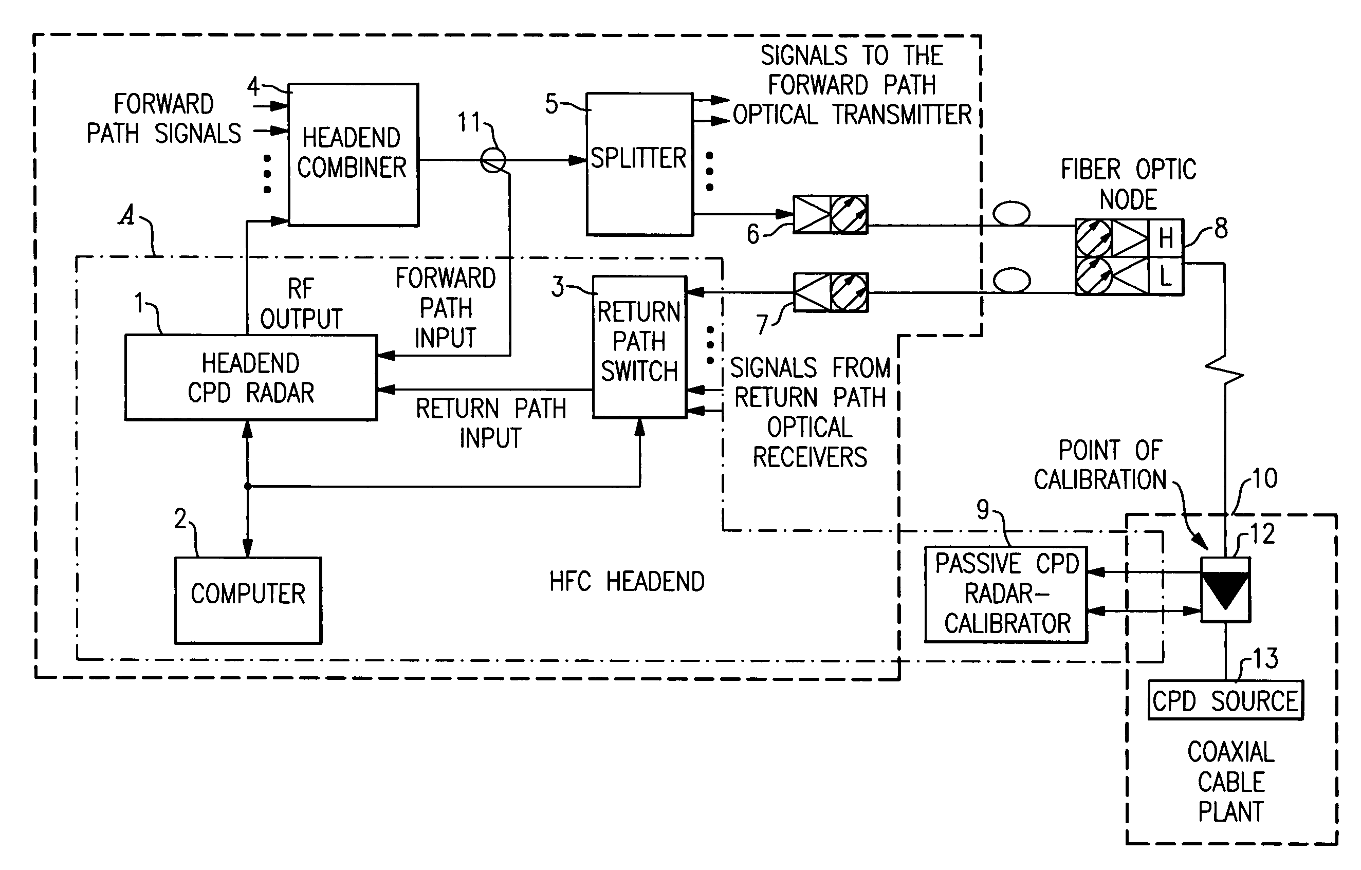
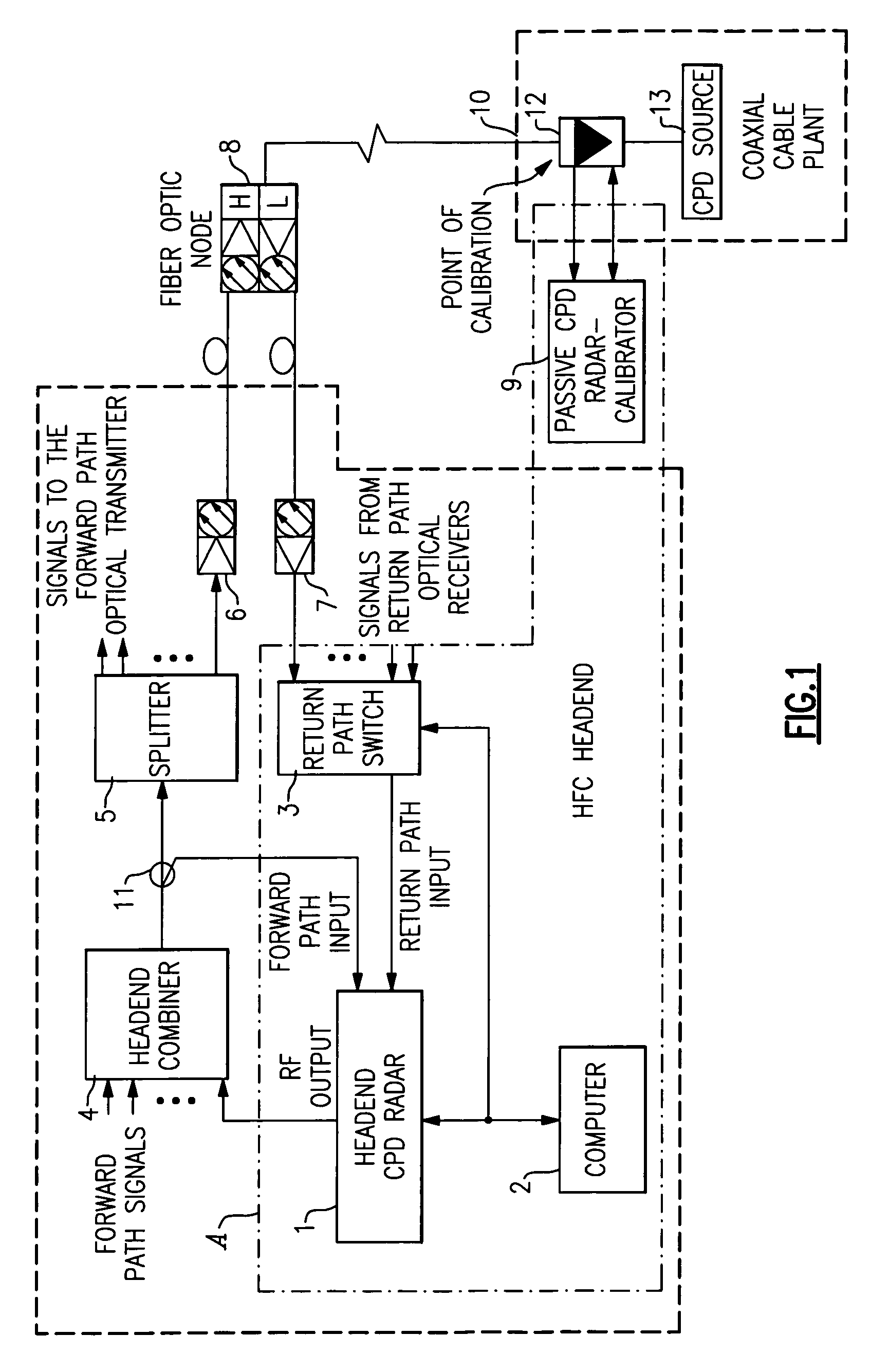
[0054]FIG. 1 shows a simplified block diagram of a preferred embodiment of a CPD pinpointing system A of the present invention. System A is incorporated into an HFC headend and a coaxial cable portion of an HFC cable TV network. System A includes the following equipment connected at the headend: a headend CPD radar unit 1, a return path switch 3, and a computer 2. System A further includes equipment connected directly to the coaxial cable portion of the network—a portable passive CPD radar-calibrator unit 9. The general headend equipment includes a headend combiner 4 for combining forward path signals (i.e., analog and digital TV program signals), a signal splitter 5 for delivering the forward path signals to a plurality of optical nodes, a plurality of optical transmitters 6 for transmitting the forward path signals to fiber optic nodes in the fiber optic portion of the HFC network, and a plurality of optical receivers 7 for receiving return path signals from the optical nodes and ...


PUM


Abstract

A system for pinpointing CDP sources in a two-way HFC CATV network comprises a headend CPD radar unit, a return path switch, and a computer. The radar unit is coupled to a headend combiner. The return path switch is coupled between the nodes of the CATV network and the radar unit. The computer is connected to the radar unit and the return path switch. The computer controls the radar unit and switch and causes them to perform constant sequential CPD monitoring of the nodes of the network. The system further comprises a portable radar-calibrator unit that is carried into the field and connected to various points along the coaxial cable portion of the network. The portable radar unit is used to detect CPD sources in the field and to calibrate the network as to time delay. The portable unit communicates with the headend radar unit through the CATV network.

Description

CROSS-REFERENCE TO RELATED APPLICATIONS[0001]This application claims the benefit of U.S. Provisional Application No. 60 / 655,191, filed Feb. 22, 2005, and U.S. Provisional Application No. 60 / 727,931, filed Oct. 18, 2005.BACKGROUND OF THE INVENTION[0002]The present invention relates generally to CATV network monitoring systems, and more particularly to methods and apparatus for pinpointing sources of common path distortion (CPD) or passive intermodulation distortion (PIM) in a two-way broad band hybrid fiber-coax (HFC) network.[0003]One form of distortion in a modern two-way HFC CATV network is common path distortion (CPD). This distortion is the result of intermodulation of forward path (or down stream) signals at components in the common path like connectors, taps, terminations, etc. due to the “diode effect” caused by corrosion (see article “Common Path Distortions Explained, Bharat Patel, www.scte.org / chapters / newenland / -reference / cpd / cpd2htm). CPD produces composite triple beat (...

Claims


Application Information

Patent Timeline
Patent Type & Authority Patents(United States)
IPC IPC(8): H04N7/173H04N17/00
CPCH04N17/00
Inventor ZINEVITCH, VICTOR M.
Owner ARCOM DIGITAL
Why Eureka
Try Eureka