Foam core imaging element with gradient density core

a technology of gradient density and support sheet, which is applied in thermography, instruments, photosensitive materials, etc., can solve the problems of low consumer acceptance, smudging and uneven print density, and suffer from image media, etc., and achieve excellent smoothness, superior support sheet, and high stiffness

Inactive Publication Date: 2009-09-08
EASTMAN KODAK CO
View PDF49 Cites 42 Cited by
  • Summary
  • Abstract
  • Description
  • Claims
  • Application Information

AI Technical Summary

Benefits of technology

[0024]This invention has numerous advantages, not all of which are incorporated into a single embodiment. This invention provides a superior support sheet. Specifically, it provides a support sheet of high stiffness, excellent smoothness, high opacity, whiteness, and excellent humidity curl resistance. It also provides a support sheet that can be manufactured using a single in-line operation. It also provides a support that can be effectively recycled. The support can be manufactured in a single in-line operation. This significantly lowers element manufacturing costs and would eliminate disadvantages in the manufacturing of the current generation of support sheets including very tight moisture specifications in the raw base and specifications to minimize pits during resin coating. It is an objective of this invention to use foam at the core of the imaging base, with high modulus flange layers that provide the needed stiffness surrounding the foam core on either side. Using this approach, many new features of the imaging base may be exploited, and restrictions in manufacturing eliminated. These and other advantages will be apparent from the detailed description below.

Problems solved by technology

Supports with properties outside the typical range for ‘imaging media’ suffer low consumer acceptance.
If the ink is not absorbed quickly, the elements block or stick together when stacked against subsequent prints and exhibit smudging and uneven print density.
Although raw paper base is typically a high modulus, low cost material, there exist significant environmental issues with the paper manufacturing process.
Current photographic papers cannot be recycled because they are composites of polyethylene and raw paper base and, as such, cannot be recycled using polymer recovery processes or paper recovery processes.
Foams have also found limited application in imaging media.
There are several problems with this, however.
It is known by those versed in the art of foaming that it is very difficult to make thin uniform foamed films with substantial reduction in density especially in the thickness range noted above.
While this process provides improvements in the area of solid films such a process does not yield foam films of sufficient smoothness for imaging purposes.
While such a device is useful in making smooth surfaced solid films on both sides simultaneously, utility in making a smooth surface foamed film with control of the foam void size is very limited.
While these processes are useful in their own right, they are not suitable for making imaging materials from foamed polyolefins, specifically polypropylenes.
While this approach is useful and provides a smooth imaging element it is very costly and the production rates are slow and difficult to maintain because of flange layer thickness.

Method used


Image

  • Foam core imaging element with gradient density core
  • Foam core imaging element with gradient density core

Examples


example 1

Control Foam Core

[0138]In this example, polypropylene foam of caliper 231.14 μm and density 0.54 gm / cm3 was obtained from a commercial source. This was then extrusion resin coated on both sides using a flat sheet die. The upper flange, on the face or imaging layer side of the foam, was coextrusion coated with two layers. The layer closer to the foam was coated at 12 gm / m2 coverage, at a melt temperature of 274° C., and comprised approximately 10% anatase TiO2, 20% Mistron CB Talc (from Luzenac America), 20% PA609 (amorphous organic polymer from Exxon Mobil) and 50% PF611 (polypropylene homopolymer—extrusion coating grade from Basell). The skin layer, that is, the layer furthest from the foam, was coated at 12 gm / m2 coverage, at a melt temperature of 300 C, and comprised approximately 18% TiO2, 4.5% ZnO, and 78.5% D4002 P (low density polyethylene from Eastman Chemical Company). The lower flange on the wire side of the foam was monoextrusion coated at 300 C melt temperature. The lowe...

example 2

Smooth Foam Element of Invention

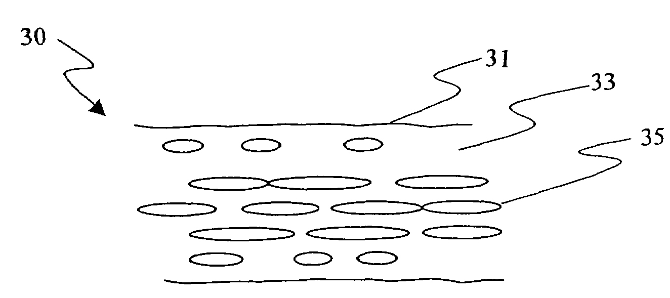
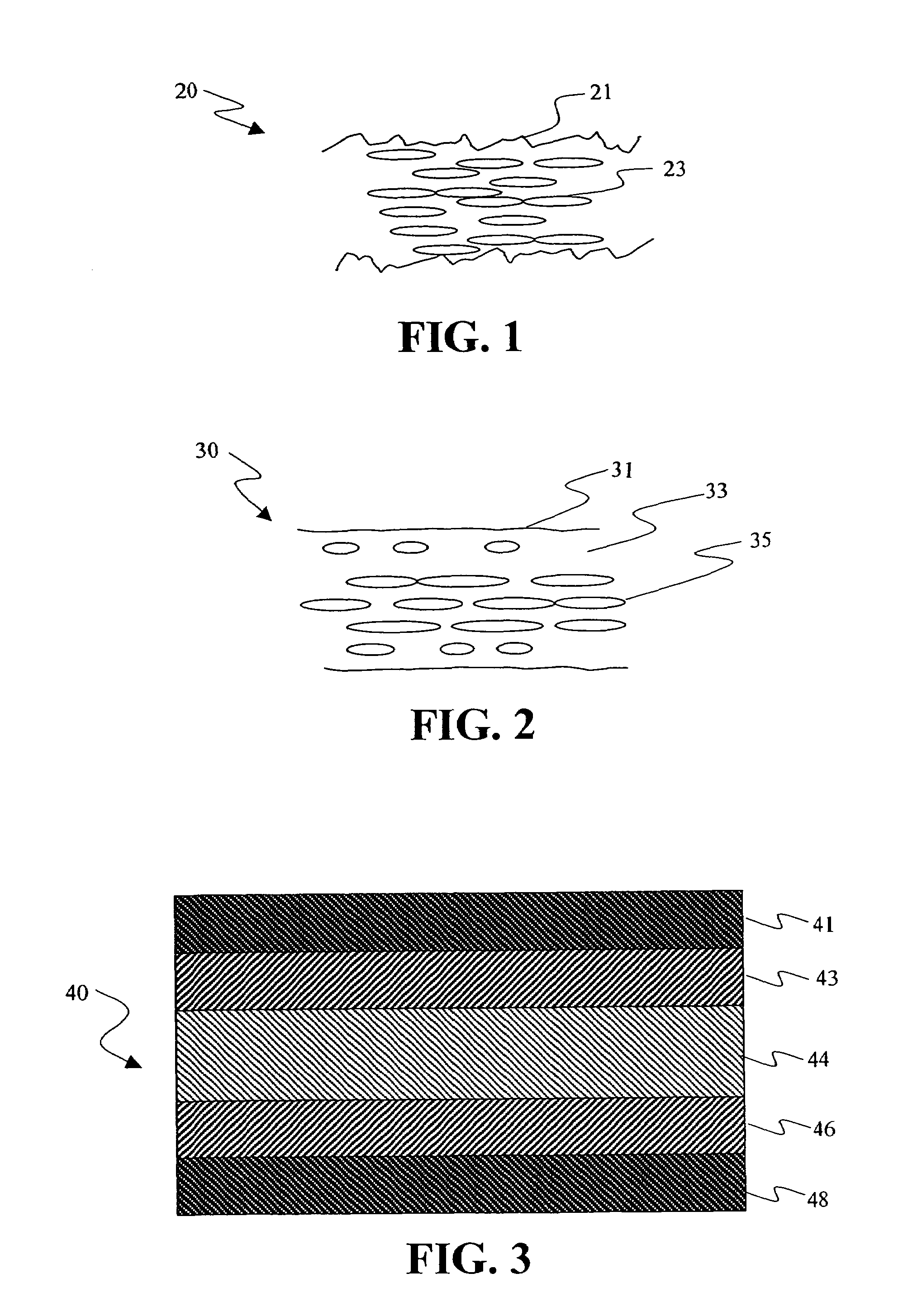
[0139]Example 2 was a foamed polypropylene sheet with a basis weight of 574.5 gm / m2 and an average sheet caliper of 758.7 μm in which there was a near instantaneous control of the polymer's surface diffusion rate of the image layer side of the cast polymer sheet and then followed by bulk heat transfer on the balance of the sheet. This instantaneous control was accomplished by controlling the dimensionless time (t*) spent by the extrudate prior to its coming into contact with the high heat transfer surface. For this Example, the t* was approximately 0.013. The foam core sheet was made with a 90 weight %, of a low melt strength linear polypropylene from Huntsman corporation (P4G4Z-011) with a melt flow rate of 12 gms. polymer extruded / 10 min. and 7.5 weight % of high melt strength polypropylene (Dow D114.01) with a melt flow rate of 0.42 gms. polymer extruded / 10 min. The overall melt strength of the resin blend is less than 10 cN at 200° C. An endotherm...

example 3

Foam Core Without Gradient—Longer Distance from Die to High Heat Transfer Surface

[0140]Example 3 was a foamed polypropylene sheet using the same material composition as example 2 .The only difference was that quenching was done with the high heat transfer surface approximately 2.5 times further away from the die slot exit than that used to make example 2. The basis weight of the cast sheet sample was 577.31 gm / m2 and average sheet caliper was 771.65 μm. This cast sample was then oriented uniaxially using a stretch ratio of 6 using the same conditions as example 2. The core sample was then melt extruded with an upper and low flange as describe in sample 1.


PUM

PropertyMeasurementUnit
surface roughnessaaaaaaaaaa
Raaaaaaaaaaa
surface roughnessaaaaaaaaaa

Abstract

The invention relates to a base comprising a closed cell foam core sheet having a closed cell foam layer with a density gradient between the center of the core and the surfaces of the core. The invention also relates to a method of making such a base by adding a first concentration of a first blowing agent to a first polymer to form a first mixture, adding a second concentration of a second blowing agent to a second polymer to form a second mixture, and extruding the mixtures to form the closed cell foam core sheet. The invention also relates to a method of making such a closed cell foam core sheet base comprising the steps of adding a blowing agent to a polymer to form a mixture, melting the mixture, extruding the mixture from a die, and rapidly quenching the mixture against a high heat transfer surface.

Description

FIELD OF THE INVENTION[0001]This invention relates to foam core supports for article, preferably an imaging elements.BACKGROUND OF THE INVENTION[0002]In order for a print imaging support to be widely accepted by the consumer for imaging applications, it has to meet requirements for preferred basis weight, caliper, stiffness, smoothness, gloss, whiteness, and opacity. Supports with properties outside the typical range for ‘imaging media’ suffer low consumer acceptance.[0003]In addition to these fundamental requirements, imaging supports are also subject to other specific requirements depending upon the mode of image formation onto the support. For example, in the formation of photographic paper, it is important that the photographic paper be resistant to penetration by liquid processing chemicals without which a stain appears on the print border accompanied by a severe loss in image quality. In the formation of ‘photo-quality’ ink jet paper, it is important that the paper is readily ...

Claims


Application Information

Patent Timeline
Patent Type & Authority Patents(United States)
IPC IPC(8): B41B5/00B29C44/22B32B3/00B32B3/26B32B5/18B32B9/00B41M5/41G03C1/79G03G7/00
CPCB29C44/22B32B5/18G03C1/79G03G7/008B41M5/41Y10T428/24802B41M2205/32Y10T428/249956Y10T428/249976Y10T428/249961Y10T428/24996Y10T428/249987Y10T428/249993Y10T428/249958Y10T428/249964Y10T428/249981Y10T428/249953B32B2307/722B32B27/36B32B27/32B32B2266/08B32B5/32B32B2307/75B32B2307/518
Inventor AYLWARD, PETER T.DONTULA, NARASIMHARAOHEATH, TERRY A.BOMBA, RICHARD D.BENSON, JOHN E.
Owner EASTMAN KODAK CO
Why Eureka
Try Eureka