Method of controlled remelting of or laser metal forming on the surface of an article

a technology of laser metal forming and controlled remelting, which is applied in the direction of machines/engines, manufacturing tools, mechanical equipment, etc., can solve the problems of reducing stress and extending the life of components, and achieves the effect of enhancing functionality and fast parallel processing

Inactive Publication Date: 2009-09-08
ANSALDO ENERGIA IP UK LTD
View PDF35 Cites 41 Cited by
  • Summary
  • Abstract
  • Description
  • Claims
  • Application Information

AI Technical Summary

Benefits of technology

[0020]The method can be used for remelting substrate material in order to re-establish a single crystal microstructure in the surface zones of the substrate, to transform a previously polycrystalline surface layer into single crystal material, to coat single crystal articles with a single crystal coating or for the repair of single crystal turbine components. Due to matched thermo-physical properties of solidified and base material the method leads to reduced stress and therefore to greater lifetime of the components.
[0021]With the online monitoring system and using automatic feed-back control of at least one process parameter such as laser power it is possible to establish and maintain optimum process conditions. In this favorable case the columnar to equiaxed transition (CET) and melt pool convection are avoided and a temperature field is created in the melt pool which leads to defect-free, epitaxial growth of the deposited material. Thus, it is possible to add new material without creation of grain boundaries. Beside the laser power process parameters like the relative speed between laser beam and the substrate, the carrier gas flow and mass feed rate of added material can be controlled.
[0024]The online feed back control of the laser power is decoupled from the main process control by means of a separate microprocessor. This allows faster parallel processing in real-time, i.e. independent from the operating system.
[0025]In another embodiment post-processing of the optical signal from the melt pool is used for quality control: The analysis of the measured data allows optimizing process parameters such that a desired microstructure is obtained. Recording of monitoring signals serves also for documentation purposes and for ensuring consistent product quality.
[0026]Moreover, dedicated commercially available software tools with enhanced functionality can be used for the realization of the control system. As a consequence short loop times and advanced PID control features such as gain scheduling can be realized.

Problems solved by technology

Due to matched thermo-physical properties of solidified and base material the method leads to reduced stress and therefore to greater lifetime of the components.

Method used


Image

  • Method of controlled remelting of or laser metal forming on the surface of an article
  • Method of controlled remelting of or laser metal forming on the surface of an article
  • Method of controlled remelting of or laser metal forming on the surface of an article

Examples


Embodiment Construction

[0034]Referring to the drawing figures, like reference numerals designate identical or corresponding elements throughout the several figures.

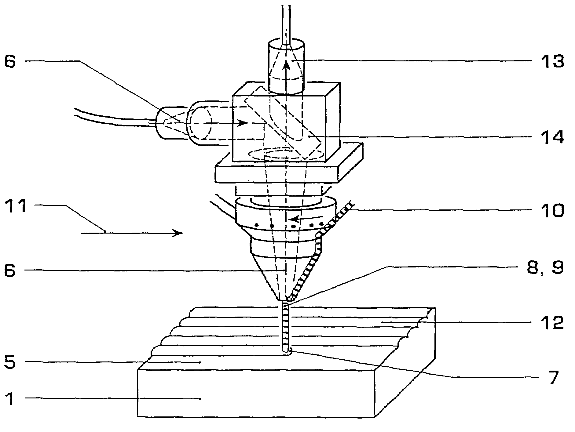
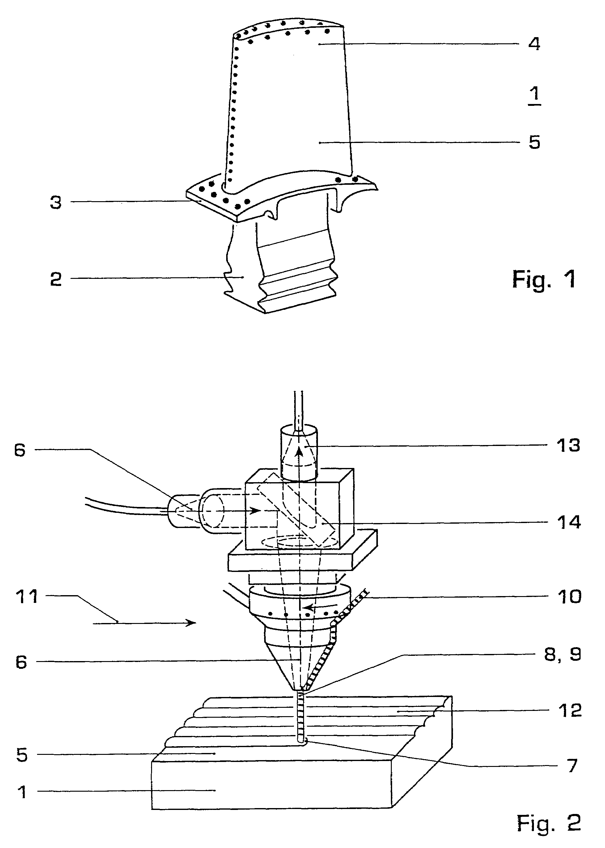
[0035]FIG. 1 shows a single crystal (SX) or directionally solidified (DS) article 1 such as blades or vanes of gas turbine engines, the gas turbine blade comprising a root portion 2, a platform 3 and a blade 4 and having a surface 5. The article 1 can as an example be made from a nickel or cobalt based super alloy. Investment casting methods for producing such SX or DS articles are known e.g. from U.S. Pat. No. 4,96,501, U.S. Pat. No. 3,690,367 or EP-A1-0 749 790, which are incorporated herein by reference. These articles 1 are normally made from a nickel or cobalt base super alloy.

[0036]The herein disclosed method can be used for remelting substrate material of the article 1 in order to re-establish a single crystal (SX) microstructure in the surface zones of the substrate or to transform a previously polycrystalline surface layer into SX mate...


PUM

PropertyMeasurementUnit
diameteraaaaaaaaaa
temperatureaaaaaaaaaa
optical signalaaaaaaaaaa

Abstract

A method for controlled remelting of or laser metal forming on the surface (5) of an article (1) can include moving a light source and a signal capturing apparatus over the article (1). The light source having a specific power can be used to melt the surface (5) of the article (1) locally and to form a melt pool (7). Thereby an optical signal (13) is captured by the signal capturing apparatus from the melt pool (7), and the monitored optical signal (13) is used for the determination of temperature and temperature fluctuations as properties of the melt pool (7). Furthermore, a control system (16) with a feedback circuit is used to adjust at least one process parameter such as the power of the light source such that desired melt pool properties are obtained. Subsequently the melt pool (7) solidifies.

Description

[0001]This application is a Continuation of, and claims priority under 35 U.S.C. §120 to, International application number PCT / CH03 / 00098, filed 10 Feb. 2003, and claims priority under 35 U.S.C. §119 to European application number 024 05 126.0, filed 20 Feb. 2002, the entireties of which are incorporated by reference herein.BACKGROUND OF THE INVENTION[0002]1. Field of the Invention[0003]The invention relates to methods of controlled remelting of or laser metal forming on the surface of articles.[0004]2. Brief Description of the Related Art[0005]In the last years laser metal forming (LMF) has been introduced in industrial manufacturing. Laser metal forming is a process where a high power laser locally melts a focused stream of metal powder or a metal wire 20 onto a substrate. In this way material can be added to the underlying part. The method is suitable for controlled material build-up and the laser generated parts are characterized by a dense microstructure which is usually free o...

Claims


Application Information

Patent Timeline
Patent Type & Authority Patents(United States)
IPC IPC(8): B23K26/03B23K26/34C23C4/12C23C26/02F01D5/00F01D5/28
CPCB23K26/032B23K26/034B23P6/007C23C4/12C23C26/02C30B13/24B23K26/0012F01D5/286B23K26/0081B23K26/3213B23K26/345B23K26/0009C30B29/52B23K26/0006B23K26/32B23K26/342B23K26/354B23K2103/26B23K2103/50
Inventor HOEBEL, MATTHIASFEHRMANN, BERND
Owner ANSALDO ENERGIA IP UK LTD
Why Eureka
Try Eureka