Carrier phase synchronization system for improved amplitude modulation and television broadcast reception

a carrier phase synchronization and amplitude modulation technology, applied in the field of communications, can solve the problems of inability to achieve such separation for amplitude-modulated (am) radio stations, concurrent distortion, and high modulation effects, and achieve the effect of reducing distortion effects

Inactive Publication Date: 2009-09-08
UT BATTELLE LLC
View PDF1 Cites 11 Cited by
  • Summary
  • Abstract
  • Description
  • Claims
  • Application Information

AI Technical Summary

Benefits of technology

[0013]According to another aspect of the invention, a method comprises synchronizing carrier phases of a group of co-channel amplitude-modulated broadcast signals, wherein synchronizing includes feeding a reference phase output from a multichannel receiver to a phase lock loop and wherein synchronizing includes substantial elimination of audible and sub-audible beats between a local desired station's carrier signal and one or more distant interfering stations' carriers and maintaining a predetermined phase relationship between said carrier signals. According to another aspect of the invention, a method comprises synchronizing the phase of a carrier frequency of a broadcast signal with the phase of a remote reference frequency, wherein synchronizing the phases of carrier frequencies of the group of co-channel amplitude-modulated broadcast signals includes synchronizing the phases of carrier frequencies of the group of co-channel amplitude-modulated broadcast signals to the phase of a remote reference frequency; synchronizing the phase of another carrier frequency of another broadcast signal with the phase of the remote reference frequency, wherein both the carrier frequency and the another carrier frequency are of a same nominal frequency; modulating both the carrier of the broadcast signal and the another carrier of the another broadcast signal with a common audio program feed, wherein the modulation of the carrier of the broadcast signal and the modulation of the another carrier of the another broadcast signal are substantially equally delayed from a central network source; augmenting at least one member selected from the group consisting of the broadcast signal and the another broadcast signal with a repeater of the same nominal frequency; and monitoring a master skywave signal from the central network source. According to another aspect of the invention, an apparatus comprises: a first multichannel receiver for detecting the phase of a reference signal; a first phase comparator coupled to the first multichannel reference signal receiver; a first voltage-controlled oscillator coupled to the first phase comparator; a first amplitude-modulated radio-frequency output coupled to the first voltage-controlled oscillator; a second multichannel receiver for detecting the phase of a reference signal; a second phase comparator coupled to the second multichannel reference signal receiver; a second voltage-controlled oscillator coupled to the second phase comparator; and a second amplitude-modulated radio-frequency output coupled to the second voltage-controlled oscillator, wherein the first amplitude-modulated radio-frequency output and the second amplitude-modulated radio-frequency output provide a group of co-channel signals whose carrier frequencies and phases thereof are synchronized to: (a) substantially eliminate audible and sub-audible beats between a local desired station's carrier signal and one or more interfering stations' carriers; and (b) to substantially reduce distortion effects in the signals as received in the coverage area overlapped by the two or more signals.

Problems solved by technology

Perhaps the major source of interference to broadcasting stations of these types are the co-channel signals from similar stations in adjacent areas of the country.
However, this scheme is practical only because of the considerable width (6 MHz) of the TV channels; no such separation is feasible for amplitude-modulated (AM) radio stations, whose channel allocations are only 10 kHz in total width!
Unfortunately, in areas that are located far from the local transmitter (i.e., the desired station), distant station carrier-beat components usually cause fast fluttering-type modulations of, and / or large-amplitude swishing sounds in, the desired station's audio at the receiver and concurrent distortion of the audio modulation from the distant station(s), even if they are sub-Hertz in nature, since the received desired station's carrier's amplitude and phase are noticeably modulated by the distant station's carrier signals.
However, the typical AM radio receiver's automatic gain-control (AGC), also called “automatic volume control” (“AVC”), usually responds far too slowly to “average out” or suppress these beat modulations; thus, these highly annoying modulation effects are largely passed on intact to the listener.
These beat-related effects are the principal factor in the degradation of evening and nighttime AM fringe-area reception quality and the resulting loss of listeners for virtually all AM stations.
Heretofore, the requirements of reducing co-channel interference and mitigating beat frequency related effects have not been fully met.

Method used


Image

  • Carrier phase synchronization system for improved amplitude modulation and television broadcast reception
  • Carrier phase synchronization system for improved amplitude modulation and television broadcast reception
  • Carrier phase synchronization system for improved amplitude modulation and television broadcast reception

Examples


example 1

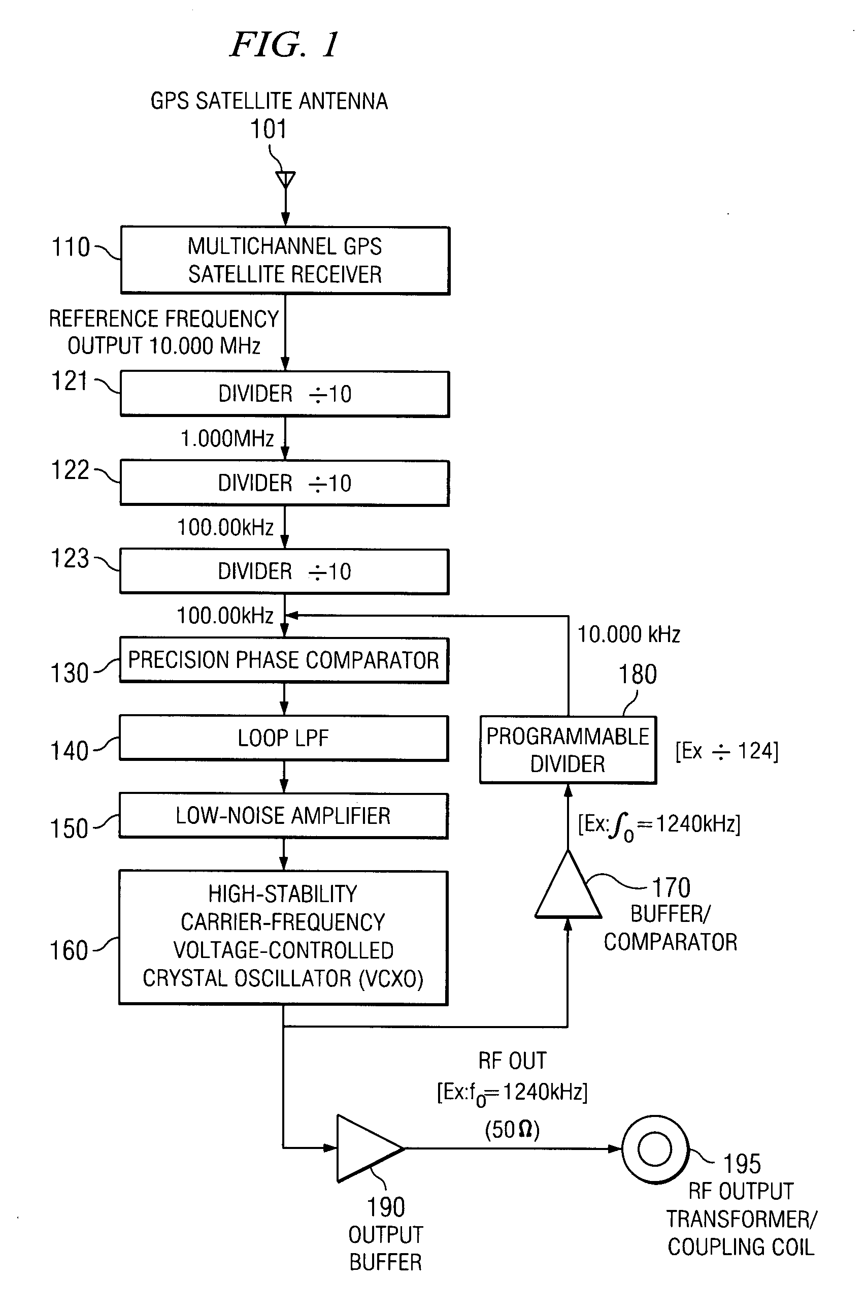
[0055]A basic configuration of the GPS-disciplined oscillator is simple, as shown in FIG. 1. A GPS satellite antenna 101 is connected to a multichannel GPS satellite receiver 110. A reference frequency output from the multichannel GPS satellite receiver 110 is fed to a first divider 121. The output from the first divider 121 is fed to a second divider 122. The output from the second divider 122 is fed to a third divider 123. The output from the third divider 123 is fed to a phase comparator 130. A loop low-pass filter 140 is coupled to the phase comparator 130. A low-noise amplifier 150 is coupled to the loop low-pass filter 140. A voltage-controlled crystal oscillator 160 (VCXO) is coupled to the low-noise amplifier 150. The output of the VCXO 160 is sent to the phase comparator 130 via a buffer / comparator 170 and a programmable divider 180. The output of the VCXO 160 is also sent to a transformer / coupling coil 195 via an RF output buffer 190.

[0056]The oscillator 160 may be a more-...

example 2

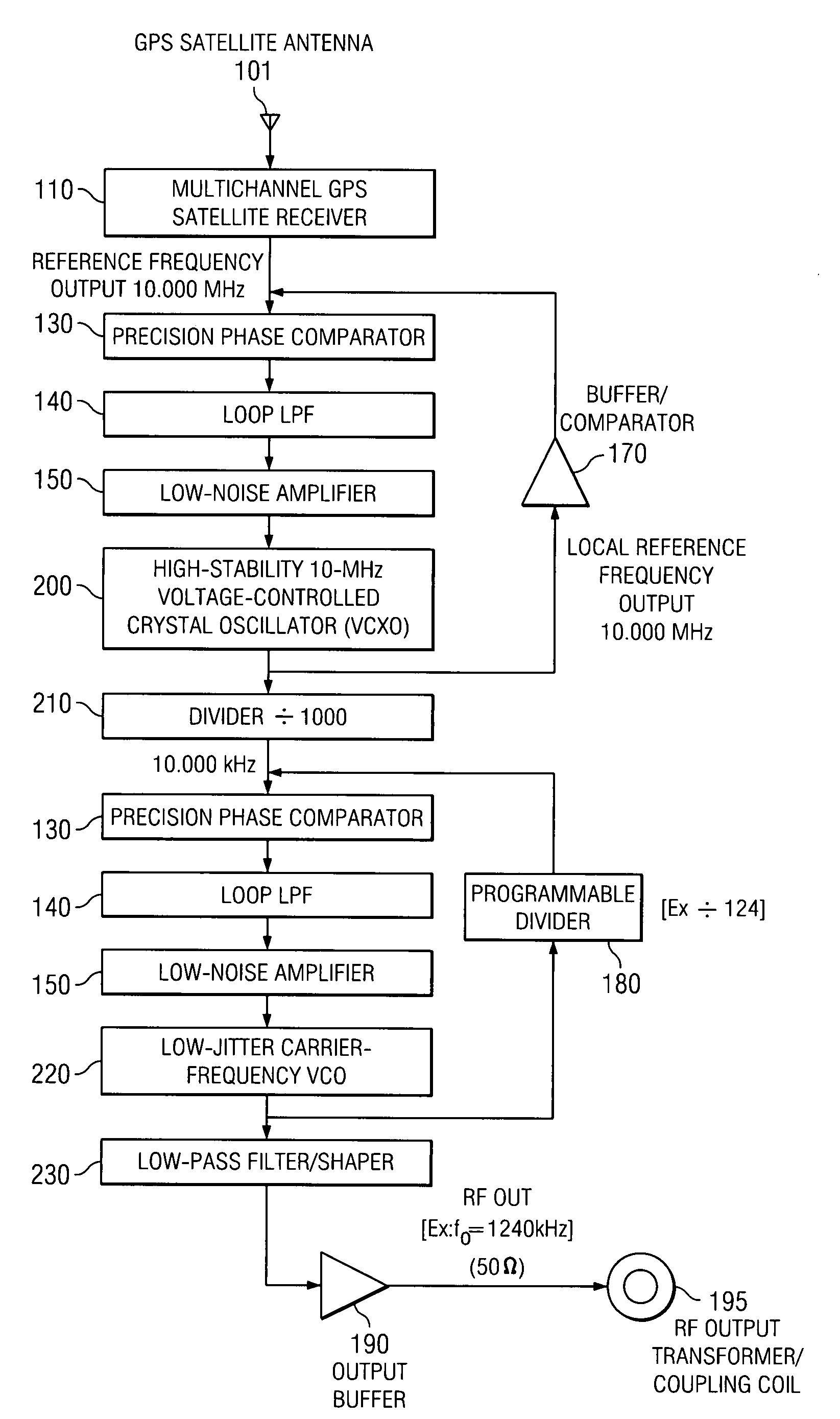
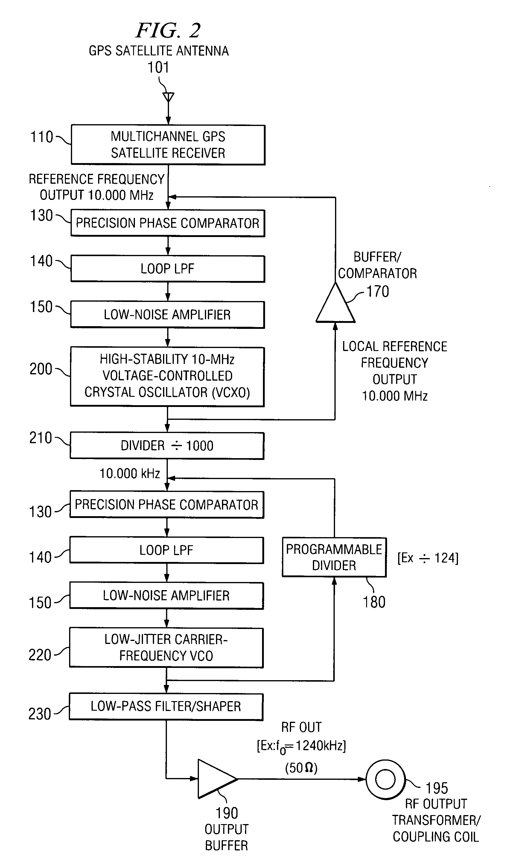
[0059]A less expensive version of the technique is illustrated in FIG. 2, where the GPS-derived reference frequency is used to discipline a local high-quality VCXO 200 (or other super-stable oscillator) with the same nominal frequency. A divider 210 is used to divide the reference frequency (here, 10.000 MHz) down to the common 10-kHz step size, and the final transmitted carrier frequency is synthesized in a conventional manner via a low-jitter VCO 220, which can be a standard square-wave oscillator. The VCO 220 drives a switched-integrator stage 230 to produce a triangular wave at the same frequency, which in turn is soft-clipped (shaped) to a very nearly sinusoidal waveform to yield the final low-distortion output carrier frequency. The principal advantage to this second approach is the elimination of the custom-manufactured carrier-frequency crystal; as a result, this design is completely standardized, regardless of the particular channel desired. An internal programmable switch ...

example 3

[0060]A third variation of the overall precision-control scheme is shown in FIG. 3, where the GPS-derived reference frequency is feed to a multiplier 310 to be multiplied to serve as the high-frequency clock (here, 200 MHz) for a fast digital numerically controlled oscillator (NCO) circuit 320, such as that included in the AD9854 chip from Analog Devices, Inc. or in numerous other similar chips from several other manufacturers (e.g., Intel, Intersil, and Philips). Here, the main NCO 320 accumulates digital phase at its clocking rate; the phase data is presented continually to a phase-to-amplitude data converter 330 [read-only memory] (“Sine-ROM”) block, which outputs a series of amplitude values corresponding to a pure sine-wave at the programmed frequency. These data words, typically at resolutions of from 8 to 14 bits, are then fed to a high-speed digital-to-analog (D / A) converter 340, which generates the stepwise analog carrier output signal. A final downstream low-pass filter / wa...


PUM


Abstract

Systems and methods are described for carrier phase synchronization for improved AM and TV broadcast reception. A method includes synchronizing the phase of a carrier frequency of a broadcast signal with the phase of a remote reference frequency. An apparatus includes a receiver to detect the phase of a reference signal; a phase comparator coupled to the reference signal-phase receiver; a voltage controlled oscillator coupled to the phase comparator; and a phase-controlled radio frequency output coupled to the voltage controlled oscillator.

Description

CROSS-REFERENCES TO RELATED APPLICATIONS[0001]This application is a continuation-in-part of, and claims a benefit of priority under 35 U.S.C. 120 from utility or design patent application U.S. Ser. No. 10 / 304,338, filed Nov. 26, 2002, now U.S. Pat. No. 7,218,696, which in-turn is a continuation of Ser. No. 09 / 860,841, filed May 17, 2001, now U.S. Pat. No. 6,563,893, the entire contents of both of which are hereby expressly incorporated herein by reference for all purposes.STATEMENT AS TO RIGHTS TO INVENTIONS MADE UNDER FEDERALLY SPONSORED RESEARCH AND DEVELOPMENT[0002]This invention was made with United States Government support awarded by the United States Department of Energy under contract to UT-Battelle, LLC. The United States has certain rights in this invention.BACKGROUND OF THE INVENTION[0003]1. Field of the Invention[0004]The invention relates generally to the field of communications. More particularly, the invention relates to AM and TV broadcast communications.[0005]2. Dis...

Claims


Application Information

Patent Timeline
Patent Type & Authority Patents(United States)
IPC IPC(8): H04L7/00H03D3/24
CPCH03D3/248H04L27/06H04L27/0014H04H20/49H04H20/12H04H20/67
Inventor SMITH, STEPHEN F.MOORE, JAMES A.
Owner UT BATTELLE LLC
Why Eureka
Try Eureka