Wear resistant coated sheet metal die and method to manufacture a wear resistant coated sheet metal forming die

a technology of coating sheet metal and forming die, which is applied in the direction of solid-state diffusion coating, cutting tools, drawing profiling tools, etc., can solve the problems of inability to finish the machining process in soft condition, slow machining and grinding after quench and temper, and high cos

Inactive Publication Date: 2009-09-15
FORD MOTOR CO
View PDF9 Cites 24 Cited by
  • Summary
  • Abstract
  • Description
  • Claims
  • Application Information

AI Technical Summary

Benefits of technology

[0010]In another embodiment, the present invention may relate to a die having a top member and a bottom member for use in sheet metal stamping operations, comprising at least one tempered and quenched steel die member having a hardness of about 40-45 Re, and a compression strength in a range of about 500-1750 MPa. At least one surface in a die member surface is machined after quenching and tempering to a desired final dimension surface to present a profile surface. The profile surface may be coated by Physical Vapor Deposition with a wear resistant coating of sufficient thickness to impart wear resistance to said profile surface. Preferably, the wear resistant coating is at least one layer applied by Physical Vapor Deposition and may be selected from CrN, AlCrN, TiCrN, TiN, TiCN, and TiAlN. Preferably, the coating is multiple la...

Problems solved by technology

Typical manufacturing processes for sheet metal stamping dies is to machine the tool to rough dimensions, quench and temper the die to the final working hardness (full hardness, typically 55-64 Rc) and then grind or machine the die to finished dimensions, Machining and grinding after quench and temper is very slow and expensive because of the high hardness of the tool.
Of particular expense is the manual grinding process which needs to be undertaken to get one surfa...

Method used


Image

  • Wear resistant coated sheet metal die and method to manufacture a wear resistant coated sheet metal forming die
  • Wear resistant coated sheet metal die and method to manufacture a wear resistant coated sheet metal forming die
  • Wear resistant coated sheet metal die and method to manufacture a wear resistant coated sheet metal forming die

Examples


Embodiment Construction

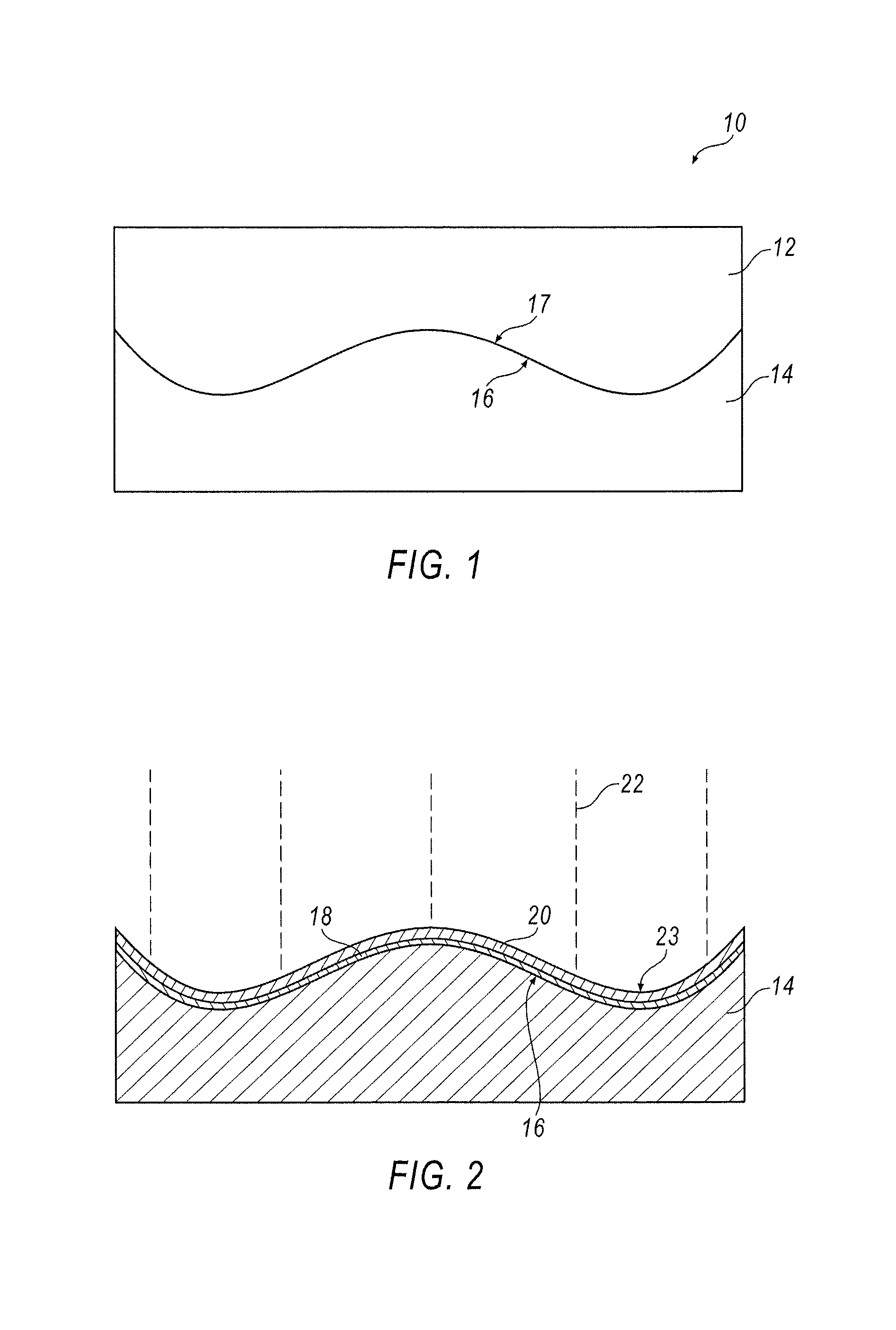
[0016]Turning now to the drawings wherein like numbers refer to like structures, and preferably to FIG. 1, there is shown therein a steel die 10 having a top member 12, a bottom member 14, and preferably complimentary surface profiles 17 and 16, respectively. The steel die members are preferably quenched and tempered at a sufficient temperature to provide members having a Rockwell hardness in the range of about 40 to 45 Rc, and a compressive strength of about 1500 to 1750 MPa. The profiles are preferably cut into the steel members after they have been subjected to quenching and tempering, as steel in the hardness of 40-45 RC range may still be machined economically and easily.

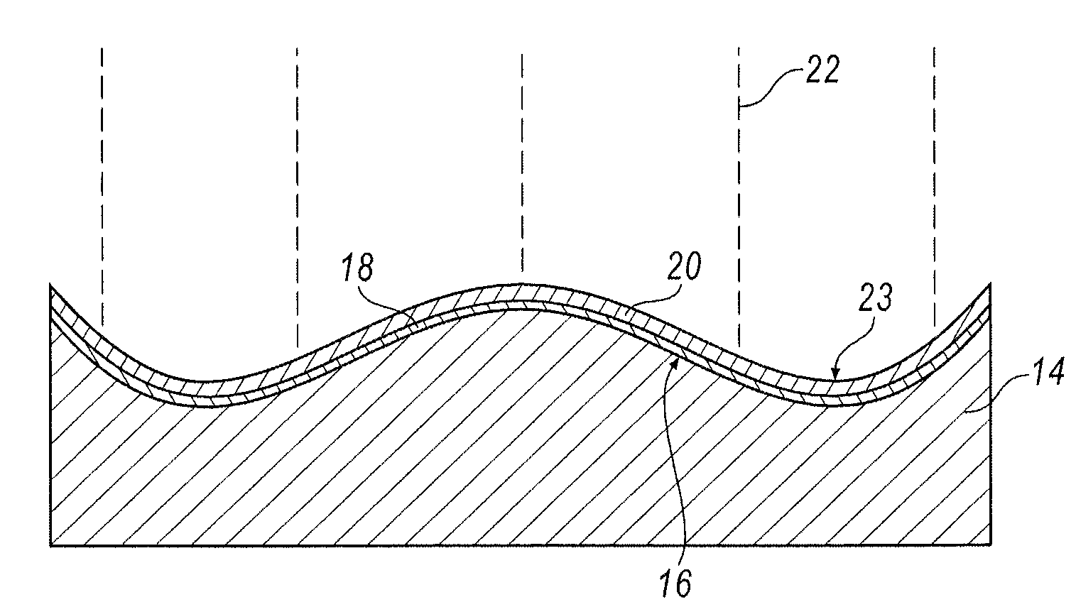
[0017]Referring now to FIG. 2, there is showing therein a cutaway side view of die member 14, showing the coating 23, being deposited onto the profile surface 16. Specifically, coating 23 is a wear resistant material, or a series of wear resistant materials, that may be applied in a single coat, or in multiple ...


PUM

PropertyMeasurementUnit
Thicknessaaaaaaaaaa
Thicknessaaaaaaaaaa
Thicknessaaaaaaaaaa

Abstract

A method to manufacture a steel die having a Physical Vapor Deposition wear resistant coating on a profile surface and a steel die formed thereby is disclosed. The steel die is subjected to quenching and tempering to achieve a Rockwell hardness in the range of about 40-45 Rc and then subjected to machining to form a profile surface. The surface is then subjected to Physical Vapor Deposition of a wear resistant coating that may be multiple layers of CrN, AlCrN, TiCrN, TiN, TiCN or TiAlN, and preferably is alternating layers of TiN—TiCN—TiN. The coating is applied at a sufficient thickness to impart wear resistance to the steel die. The steel dies are useful in sheet metal stamping operations.

Description

TECHNICAL ART[0001]Typical manufacturing processes for sheet metal stamping dies is to machine the tool to rough dimensions, quench and temper the die to the final working hardness (full hardness, typically 55-64 Rc) and then grind or machine the die to finished dimensions, Machining and grinding after quench and temper is very slow and expensive because of the high hardness of the tool. Of particular expense is the manual grinding process which needs to be undertaken to get one surface of the tool flat prior to setting the tool on a milling machine or surface grinder. Machining to finished treatment in the soft condition is not possible because the metallurgical transformations that take place during heat treatment causes dimensional changes in the tool. Tools are quenched and tempered to a high Rockwell hardness for two reasons. First, hardness at the surface promotes longevity of the tool by resisting wear. Second, hardness in the tool's cross section resists plastic deformation ...

Claims


Application Information

Patent Timeline
IPC IPC(8): B21D37/18
CPCB21D37/20
Inventor YOUNG, DARRYL L.
Owner FORD MOTOR CO
Why Eureka
Try Eureka