Hard-material-coated member excellent in durability

a hard-material coating and excellent technology, applied in the field of hard-material coating members excellent, can solve the problems of wasting steel materials in a portion of the casting member in contact with aluminum alloy, unable to meet the above-mentioned requirements, and reducing the life of the mold for plastic working, so as to improve the wear resistance of the working plane of the mold, improve the wear resistance of the mold and other members, and improve the resistance to waste by melting.

Inactive Publication Date: 2010-06-29
HITACHI METALS LTD
View PDF27 Cites 3 Cited by
  • Summary
  • Abstract
  • Description
  • Claims
  • Application Information

AI Technical Summary

Benefits of technology

[0022]As a result, it was found that by forming coating layers capable of functioning in a region from the surface of a base material to a working plane in contact with a material to be processed, as a composite layer in which the coating layers are classified according to their hardness distribution, and by adjusting the relationship among the thickness values of these layers, a very good wear resistance can be imparted to a mold for plastic working such as forging or pressing and moreover, very good resistance to waste by melting and wear resistance can be imparted to a casting member. By these results, it was confirmed that even when the thickness of the coating layers are increased in order to impart a sufficient durability to the mold for plastic working irrespective of whether the mold is for cold working or warm-hot working, the coating layers function without peeling, so that the life of the mold for plastic working is markedly improved. Moreover, by the above results, it was confirmed that in a core pin for die casting of an aluminum alloy, there are sufficiently suppressed the waste by melting of the pin caused by peeling of the coating layers by the deflection of the pin during the solidification and shrinkage of a cast product, and the wear of the pin caused by the collision of a melt at a high speed with the pin, so that the life of the core pin as casting member is markedly improved.
[0032]Conventional molds coated with TiN, VCN, CrN, TiAlN or CrAlWN by physical vapor deposition do not have a sufficient life to cope with the environment of use that has become severe in recent years. By using as a mold a member having the surface coating layer structure according to the present invention, the wear resistance of the working plane of the mold can be improved, so that the life of the mold for plastic working can be greatly improved.
[0033]Conventional casting members coated with TiN, TiCN or CrN have become unable to have a sufficient life to cope with use environment that has become severe in recent years. By using as a casting member a member having the surface coating layer structure according to the present invention, the resistance to waste by melting and wear resistance of a mold and other members can be improved, so that the life of the mold and the other members can be greatly improved.

Problems solved by technology

Therefore, a CVD method employing a coating temperature of 1,000° C. or higher has become unable to satisfy the above-mentioned requirement sufficiently because the mold is remarkably deformed during the coating and a steel-based mold material involves a problem of heat-treatment distortion caused by heat treatment such as quenching and tempering conducted after the coating.
In the case of the above-mentioned steel materials used in casting members such as molds, the steel material in a portion of the casting member in contact with the aluminum alloy is wasted by melting in a melt of the aluminum alloy to increase the iron content of the aluminum alloy melt and deteriorate the quality of a cast product.
Moreover, the waste by melting of the molds and the like causes various operational troubles.
However, since employment of a high-melting aluminum alloy as a material to be molded has become frequent for the purpose of increasing the strength of a cast product, nitriding has the following disadvantages: N in the hardened layer is easily diffused into an aluminum melt at a high temperature, so that the resistance to the waste by melting is deteriorated by the disappearance of the hardened layer, resulting in rapid progress of the waste-by-melting phenomenon.
As to a mold for plastic working, a coating layer of TiC or TiN formed by a CVD method has a high hardness and a relatively large thickness of about 10 μm and hence has satisfactory characteristics, but the precision of a mold having such a coating layer is not satisfactory because of, for example, the deformation of the mold caused by a high coating temperature.
On the other hand, the coating layer formed by a PVD method, which has been proposed in any of patent documents 1 to 5, gives a satisfactory precision to a mold but is inferior in adhesion to a layer formed by a CVD method.
Therefore, when an attempt is made to impart a sufficient durability to the mold by increasing the layer thickness, the coating layer becomes easily peelable.
Accordingly, the function of the coating layer cannot sufficiently satisfy the requirements in the use environment of molds for forging or pressing which has become severe year by year.
Therefore, the use environment of a member used in contact with the melt, such as a casting mold, has become more severe.
That is, the following troubles have come to be remarkably caused: the thermal expansion of a mold or other members by a molten metal during casting; and the deflection of the mold or the members by shrinkage thereof by application of a mold release agent after the solidification of a material to be processed or by the solidification and shrinkage of the material to be processed.
The above proposed coating layers have insufficient resistance to wear by a melt.
Since the coating layer is worn away by a fluid in a region near the gate of the mold where a melt is introduced into the mold at a high speed, the mold repairing cycle and the mold life are decreased, and the shape of a cast product is unsatisfactory.

Method used


Image

  • Hard-material-coated member excellent in durability
  • Hard-material-coated member excellent in durability

Examples


example 1

[0062]High-speed steel SKH 51 specified in JIS was prepared, maintained at 1,180° C. by heating in a vacuum, quenched by nitrogen gas cooling, and then tempered at 540 to 580° C. to be subjected to thermal refining to 64 HRC. Thereafter, the thus treated material was processed into plate-shaped test pieces with a thickness of 5 mm and a length of each side of 30 mm. Each of the test pieces was coated as a base material by PVD method.

[0063]As to a method for the coating, an arc ion plating apparatus was used. First, a bias voltage of −400 V was applied to each base material in an Ar atmosphere (pressure: 0.5 Pa) and plasma cleaning with a hot filament was conducted for 60 minutes. Then, using various metal targets as sources for vapors of metal components and a reaction gas composed of N2 gas as base and optionally CH4 gas, a film was formed at a temperature of the base material of 500° C., a reaction gas pressure of 3.0 Pa and a bias voltage of −50 V.

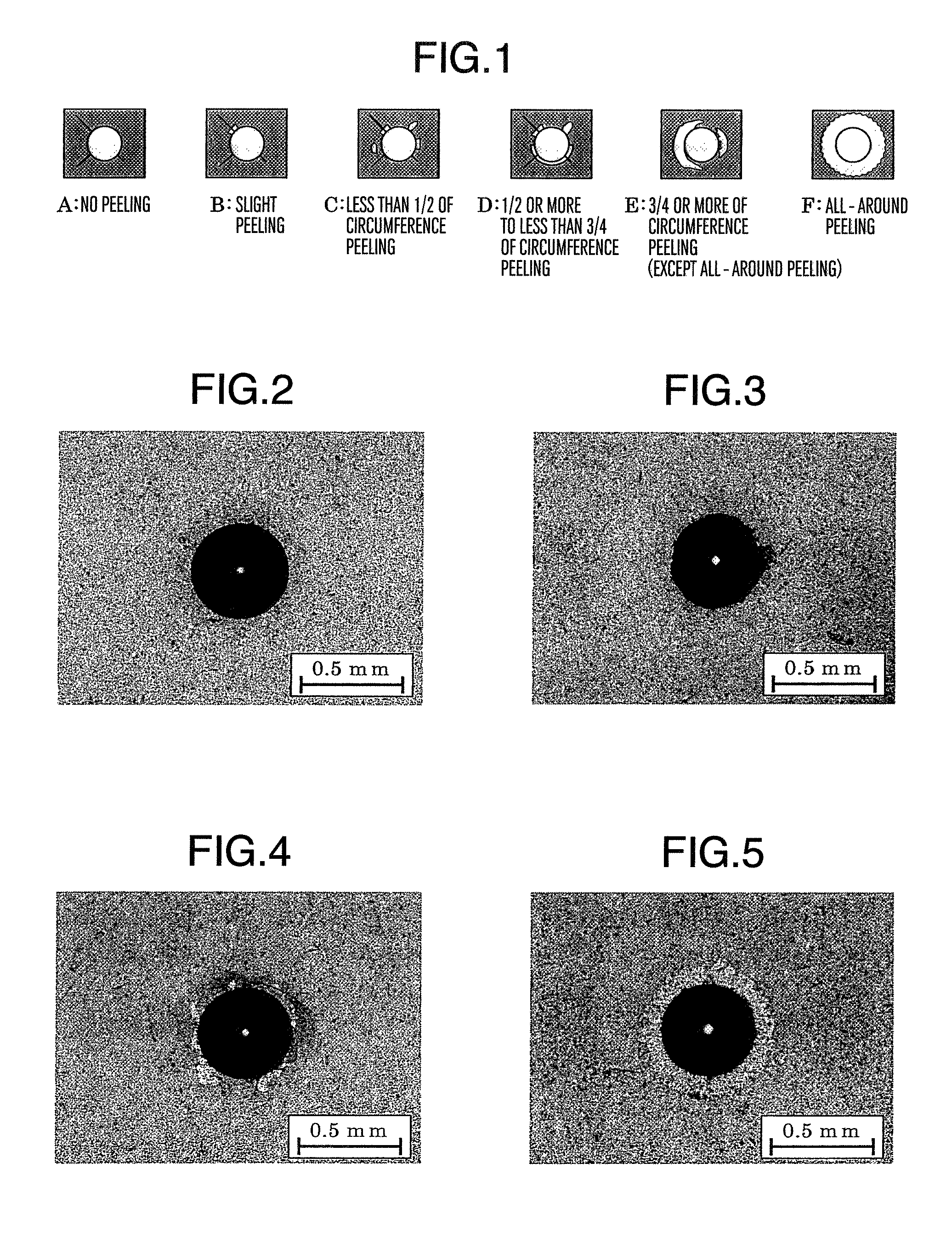
[0064]In the case of samples obt...

example 2

[0075]Next, cold-forging molds for molding a cup having a surface coating layer structure equal to those of present inventive test piece No. 3 and No. 8 in Table 1 and conventional test piece No. 23 in Table 2, respectively, were produced from SKH 51 (hardness: 64 HRC). The molds were evaluated as actual molds with respect to their life.

[0076]First, SKH 51 was roughly processed in an annealed state into a shape similar to that of a forging mold, after which it was maintained at 1,180° C. by heating in a vacuum, quenched by nitrogen gas cooling, and then tempered at 540 to 580° C. to be subjected to thermal refining to 64 HRC. Thereafter, finish processing was conducted and layers were formed by PVD method under the same conditions as in Example 1 for obtaining each of the molds described above, after conducting ion nitriding treatment in the case of test pieces to be subjected to this treatment before the coating treatment.

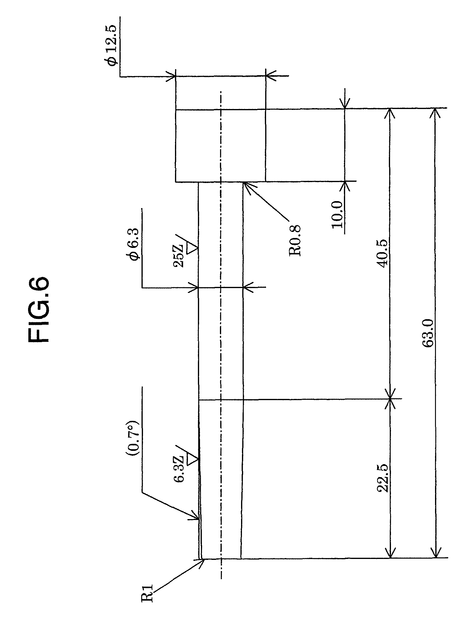
[0077]The molds produced above had a diameter of 30 mm and a...

example 3

[0080]Warm-forging punches for molding a cup having a surface coating layer structure equal to those of present inventive test piece No. 4 and No. 5 in Table 1 and conventional test piece No. 22 in Table 2, respectively, were produced and then evaluated as actual molds with respect to their life.

[0081]First, a toughness-improved material composed of high-speed steel as base and having the chemical composition shown in Table 4 was roughly processed as a base material into a shape similar to that of a mold, after which it was subjected to oil quenching from 1,080° C. and then thermal refining to 56 HRC by tempering at 600° C. Thereafter, finish processing was conducted and nitriding treatment and the formation of layers by PVD method were carried out under the same conditions as in Example 1 for obtaining each of the punches described above.

[0082]

TABLE 4Chemical composition (mass %)CSiMnCrWMoVCoFeBase0.500.150.454.201.502.001.200.75Bal-materialanceformold

[0083]The molds produced above...


PUM

PropertyMeasurementUnit
total thicknessaaaaaaaaaa
thicknessaaaaaaaaaa
thicknessaaaaaaaaaa

Abstract

There is provided a hard-material-coated member which is suitable as a long-life mold for plastic working of metals and which has a metal as base material and coating layers formed at least on its working plane by physical vapor deposition. At least three layers, i.e., a layer a) as the outermost layer, a layer c) just above the base material and a layer b) between layer a) and the layer c) are formed as coating layers. The hardness values of these layers in terms of hardness symbol HV 0.025 are as follows:2500>(the hardness of the layer a)>1000,3500>(the hardness of the layer b)>2300,2500>(the hardness of the layer c)>1000,(500+the hardness of the layer a)<(the hardness of the layer b), and(500+the hardness of the layer c)<(the hardness of the layer b); the thickness of the layer b) is smaller than that of the layer c); and the total thickness of the coating layers is 5 to 15 μm.

Description

BACKGROUND OF THE INVENTION[0001]The present invention relates to a hard-material-coated member excellent in durability which is the most suitable as, for example,(1) a mold for plastic working which is used for forging, pressing or the like and is required to have wear resistance, and(2) a casting member used in contact with a molten metal, such as a mold used for die casting or casting, a core pin, a piston ring used in an injection machine for die casting, or the like.[0002]Molds obtained by using a metal or steel, such as cold-die steel, hot-die steel, high-speed steel, a hard alloy or the like as a base material have been used for plastic working such as forging or pressing. Methods for the above working are classified into cold working in which working is conducted near room temperature and warm or hot working (hereinafter referred to also as warm-hot working) in which a material to be processed is heated at 400° C. or higher. A mold used in either of these working methods is ...

Claims


Application Information

Patent Timeline
Patent Type & Authority Patents(United States)
IPC IPC(8): B32B7/02B28B7/36B22C3/00
CPCC23C14/024C23C14/0635C23C30/005C23C14/0664C23C14/0641
Inventor INOUE, KENICHIHONDA, FUMIAKI
Owner HITACHI METALS LTD
Why Eureka
Try Eureka