Control system for multiphase rotary electric machines
a control system and multi-phase technology, applied in the direction of electronic commutators, motor/generator/converter stoppers, dynamo-electric converter control, etc., can solve the problems of increasing the number of switchings of each switching element, increasing the torque deviation, and difficult for the three-phase rotary electric machine to generate the request torqu
- Summary
- Abstract
- Description
- Claims
- Application Information
AI Technical Summary
Benefits of technology
Problems solved by technology
Method used
Image
Examples
first embodiment
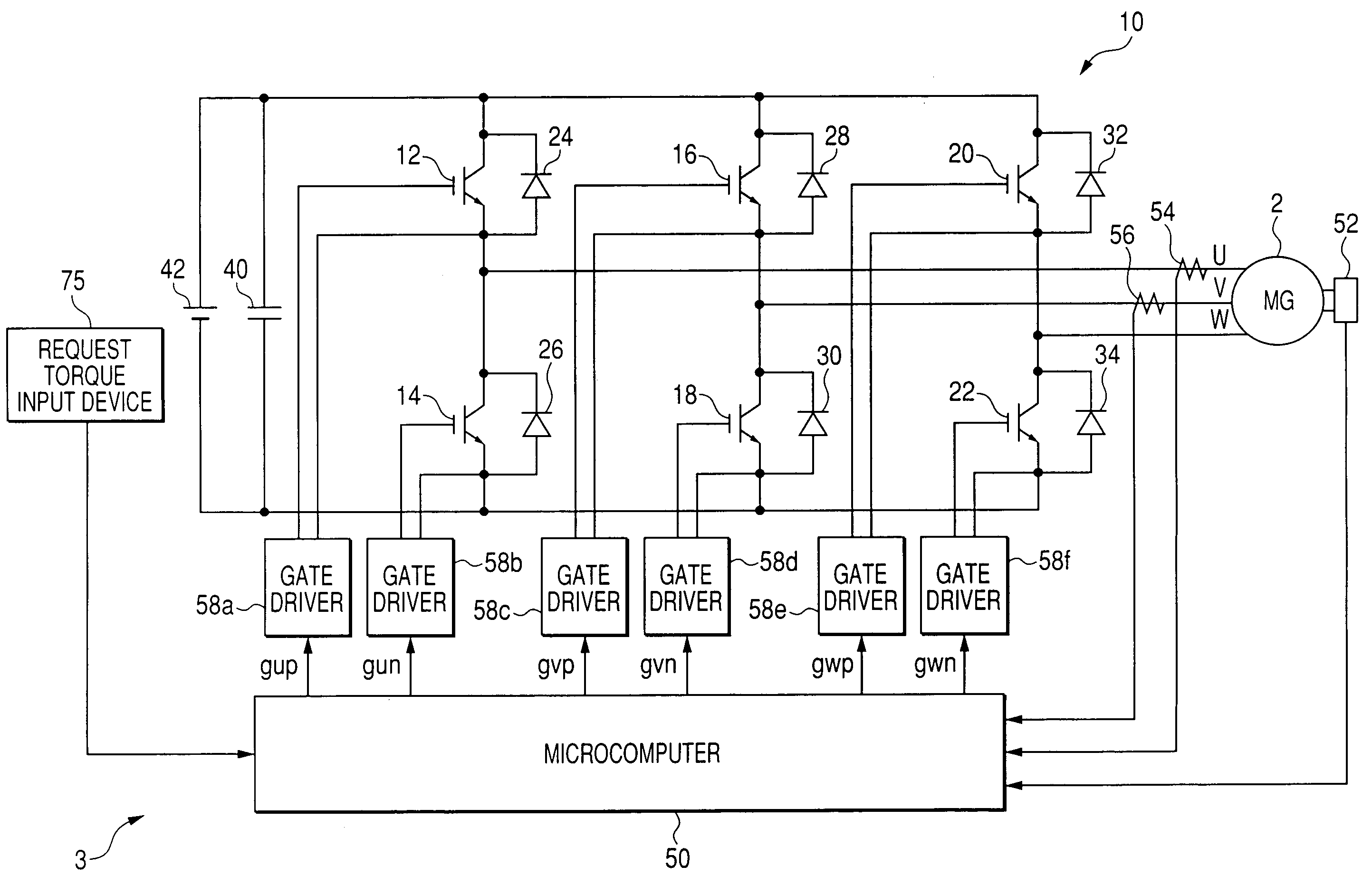
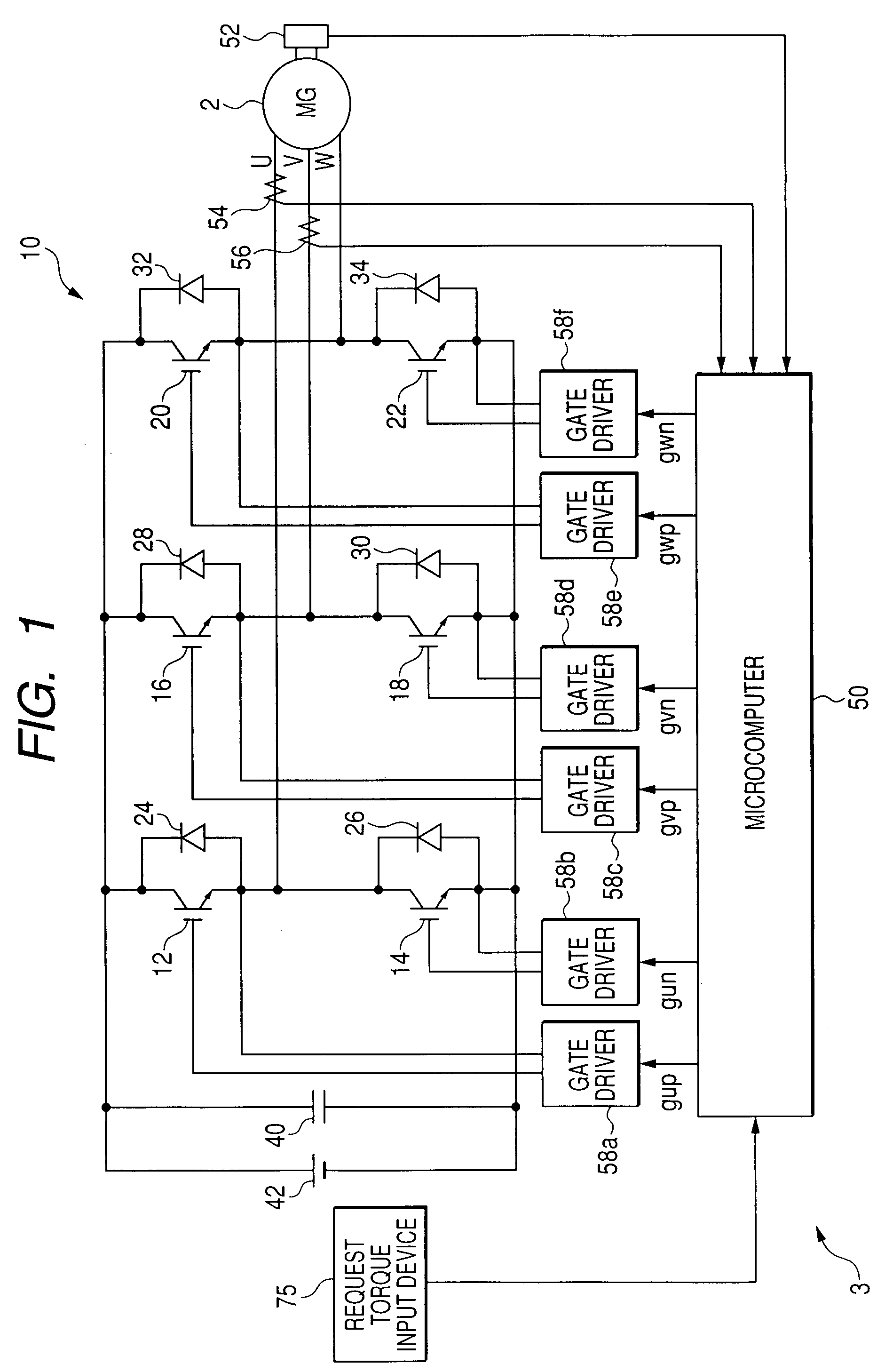
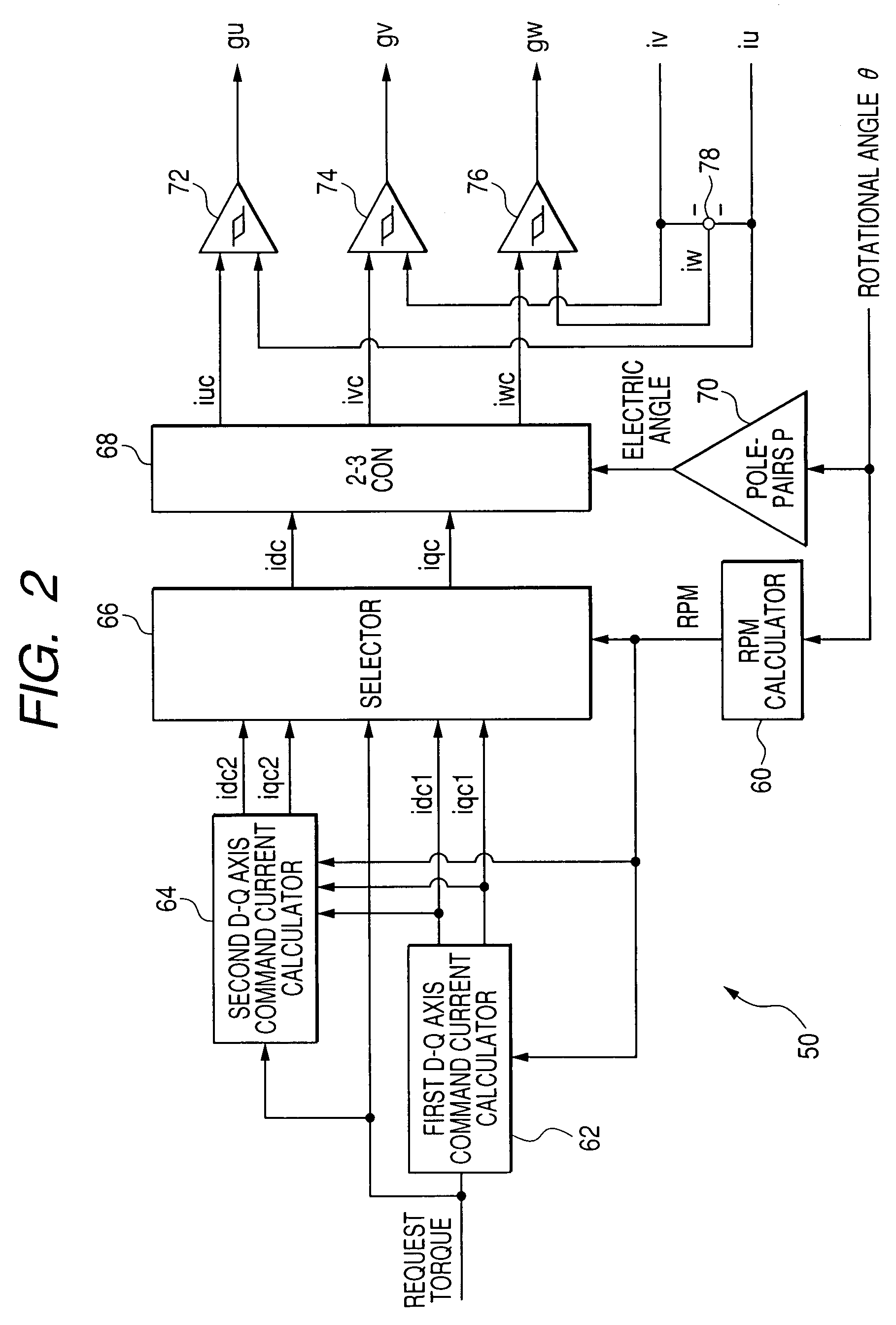
[0053]Referring to the drawings, in which like reference characters refer to like parts in several figures, particularly to FIG. 1, there is illustrated a three-phase DC (Direct Current) brushless motor, referred to simply as “motor”2 and a control system 3 for controlling the motor 2.
[0054]For example, the motor 2 is provided with an annular rotor whose rotor core is fixedly fitted around the outer periphery of a crankshaft of an engine installed in the hybrid vehicle.
[0055]The rotor core of the rotor is provided at its circumferential portion with a number of N and S pole pairs arranged at given intervals. The rotor has a direct axis (d-axis) in line with a rotor N pole center line, and has a quadrature axis (q-axis) whose phase is π / 2 radian electric angle leading with respect to a corresponding d-axis during rotation of the rotor.
[0056]The stator includes a stator core with, for example, an annular shape in its lateral cross section. The stator core is disposed around the outer ...
second embodiment
[0146]A control system for a motor according to a second embodiment of the present invention will be described hereinafter. The structure of the control system is substantially identical to that of the control system 3 according to the first embodiment.
[0147]Thus, like reference characters are assigned to like parts in the control systems according to the first and second embodiments, and therefore, descriptions of the structure of control system according to the second embodiment are omitted.
[0148]FIG. 9 schematically illustrates functional modules of a microcomputer 50A equivalent to tasks to be executed thereby according to the second embodiment.
[0149]The microcomputer 50A includes a command current calculator 80 in place of the first d-q axis command current calculator 62, the second d-q axis command current calculator 64, and the current value selector 66.
[0150]The command current calculator 80 works to calculate the first command values idc1 and iqc1 and the second command val...
third embodiment
[0174]A control system for a motor according to a third embodiment of the present invention will be described hereinafter. The structure of the control system is substantially identical to that of the control system 3 according to the first embodiment.
[0175]Thus, like reference characters are assigned to like parts in the control systems according to the first and third embodiments, and therefore, descriptions of the structure of control system according to the third embodiment are omitted.
[0176]FIG. 13 schematically illustrates functional modules of a microcomputer 50B equivalent to tasks to be executed thereby according to the third embodiment.
[0177]The microcomputer 50B includes an amplitude correction-coefficient calculator (COEFFICIENT CALCULATOR) 82, a multiplier 84, a multiplier 86, a phase correction-value calculator 88, and an adder 90 in place of the second d-q axis command current calculator 64.
[0178]A first d-q axis command current calculator 62A has first command value ...
PUM
 Abstract
Description
Claims
Application Information
 - R&D
- Intellectual Property
- Life Sciences
- Materials
- Tech Scout
- Unparalleled Data Quality
- Higher Quality Content
- 60% Fewer Hallucinations
Browse by: Latest US Patents, China's latest patents, Technical Efficacy Thesaurus, Application Domain, Technology Topic, Popular Technical Reports.
© 2025 PatSnap. All rights reserved.Legal|Privacy policy|Modern Slavery Act Transparency Statement|Sitemap|About US| Contact US: help@patsnap.com


