Dielectric ceramic, ceramic electronic element, and multilayer ceramic capacitor

a technology of electronic elements and capacitors, applied in the field of dielectric ceramics, can solve problems such as varied problems, and achieve the effects of improving sintering properties, stably using, and easy modification of dielectric properties

Active Publication Date: 2009-09-29
MURATA MFG CO LTD
View PDF16 Cites 25 Cited by
  • Summary
  • Abstract
  • Description
  • Claims
  • Application Information

AI Technical Summary

Benefits of technology

[0018]The present invention has been conceived in consideration of the above situation, and on object of the present invention is to provide a dielectric ceramic which can be stably used in a high-temperature atmosphere without degrading dielectric properties, properties of which can be easily adjusted, and which generates no electrode breakage even when a ceramic layer and a conductive film are co-fired; a ceramic electronic element using this dielectric ceramic; and a multilayer ceramic capacitor.
[0020]Hence, through intensive research carried out by the inventors of the present invention, it was found that when Ca is contained in the composition, this Ca facilitates solid solution of Sn in the Ba site. As a result, it was found that without performing a firing treatment at an extremely low oxygen partial pressure of 10−12 to 10−16 MPa, a dielectric ceramic having a high Curie temperature Tc can be obtained. In addition, in order to smoothly reduce quadrivalent Sn to divalent Sn, it is believed that thermal treatment including not only firing but also calcining is preferably performed in a predetermined low oxygen partial pressure range.
[0027]According to the dielectric ceramic of the present invention, since Ca facilitates solid solution of Sn in the Ba site, without performing a thermal treatment at an extremely low oxygen partial atmosphere, a dielectric ceramic having a high Curie temperature can be obtained. In addition, as a result, a dielectric ceramic can be obtained which has stable dielectric properties even in a high-temperature atmosphere, properties of which can be easily adjusted since the degree of freedom of firing conditions is increased, and which can prevent degradation in insulating properties.
[0029]In addition, since at least one of Mn and V in 0.02 to 2 molar parts is contained with respect to 100 molar parts of the primary component, or Si in 0.02 to 5 molar parts is contained with respect to 100 molar parts of the primary component, sintering properties can be improved.
[0030]In addition, according to the ceramic electronic element of the present invention, since the ceramic base body formed from the above dielectric ceramic includes a conductor, a ceramic electronic element can be realized which can be stably used in a high-temperature atmosphere, which can also easily change its dielectric properties by adjusting firing conditions, and which can prevent degradation in insulating properties, for example, due to the change in firing temperature.
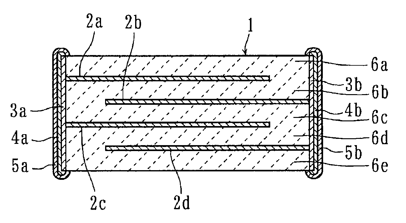
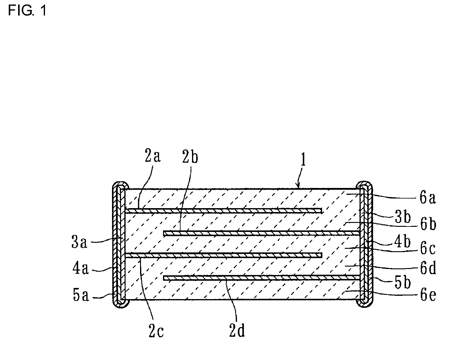
[0031]In addition, according to the multilayer ceramic capacitor of the present invention, since the ceramic layers are formed from the above dielectric ceramic, firing can be performed in a firing atmosphere at an oxygen partial pressure of approximately 10−10 to 10−12 MPa, so that besides the above-described effects, even when the thickness of internal electrodes is decreased, failures, such as electrode breakage, which are caused when the internal electrodes are sphered can be suppressed. Hence, a multilayer ceramic capacitor can be realized which can be stably used in a high-temperature atmosphere and which can be suitably used for automobile applications and the like.

Problems solved by technology

However, in order to solid-solve Sn in the B site by reducing stable quadrivalent Sn to divalent Sn, when the oxygen partial pressure in firing is extremely decreased to 10−12 to 10−16 MPa, various problems as described above occur.

Method used


Image

  • Dielectric ceramic, ceramic electronic element, and multilayer ceramic capacitor
  • Dielectric ceramic, ceramic electronic element, and multilayer ceramic capacitor

Examples


example 1

[0084]First, as ceramic raw materials, BaCO3, TiO2, CaCo3, and SnO2 were prepared. Next, these ceramic raw materials were weighed so that primary components had the compositions as shown in Table 1. Subsequently, the materials thus weighed were charged to a ball mill with PSZ balls and pure water and were sufficiently mixed and pulverized by a wet process, followed by drying, so that a mixed powder was obtained.

[0085]Next, after this mixed powder was calcined by a thermal treatment performed at a temperature of 1,000° C. for 2 hours in a reducing atmosphere containing a N2—H2 mixed gas in which the oxygen partial pressure was controlled to be 1.0×10−10.0 MPa, dry pulverization was performed, so that a powdered ceramic starting material having a primary composition represented by (Ba1-x-yCaxSny)mTiO3 was formed.

[0086]Next, after a poly(vinyl butyral)-based binder and ethanol functioning as a solvent were added to this powdered ceramic starting material, mixing and pulverizing were pe...

example 2

[0101]As ceramic raw materials, BaCO3, TiO2, CaCO3, and SnO2 were prepared as in the example 1. Next, these ceramic raw materials were weighed so that primary components had the compositions as shown in Table 2. Subsequently, the materials thus weighed were charged to a ball mill with PSZ balls and pure water and were sufficiently mixed and pulverized by a wet process, followed by drying, so that a mixed powder was obtained.

[0102]Next, this mixed powder was calcined by a thermal treatment performed at a temperature of 1,000° C. for 2 hours in a reducing atmosphere containing a N2—H2 mixed gas in which the oxygen partial pressure was controlled as shown in Table 2, and dry pulverization was then performed, so that a powdered ceramic starting material having a primary composition represented by (Ba1-x-yCaxSny)mTiO3 was formed.

[0103]Next, after an acrylic-based organic binder and ethanol functioning as a solvent were added to this powdered ceramic starting material, wet mixing was perf...

example 3

[0117]By a method and a procedure similar to those of the example 1, multilayer ceramic capacitors of sample Nos. 21 to 29 were formed so that primary components had the compositions as shown in Table 3. In this example 3, thermal treatments in calcining and firing were each performed at an oxygen partial pressures of 1.0×10−10.0 MPa.

[0118]Next, by methods similar to those of the example 1, the relative dielectric constant εr, the dielectric loss tan δ, and the Curie temperature Tc of each of the sample Nos. 21 to 29 were measured.

[0119]Table 3 shows the composition components of the sample Nos. 21 to 29 and the measurement results thereof.

[0120]

TABLE 3Oxygen partial pressureRelativeDielectric lossCurieSample(Ba1−x−yCaxSny)mTiO3(MPa)dielectrictan δtemperature TcNo.xymIn calciningIn firingconstant εr(%)(° C.)210.080.051.001.0 × 10−10.01.0 × 10−10.01,6003.0152220.100.051.001.0 × 10−10.01.0 × 10−10.01,5003.3150230.150.051.001.0 × 10−10.01.0 × 10−10.01,2003.5153240.200.051.001.0 × 10−10...


PUM

PropertyMeasurementUnit
dielectric loss tan δaaaaaaaaaa
relative dielectric constant εraaaaaaaaaa
remanent polarizationaaaaaaaaaa

Abstract

A dielectric ceramic including a perovskite compound represented by the general formula {(Ba1-x-yCaxSny)m(Ti1-zZrz)O3} as a primary component in which the x, y, z, and m satisfy 0.02≦x≦0.20, 0.02≦y≦0.20, 0≦z≦0.05, and 0.99≦m≦1.1 and is processed by a thermal treatment at a low oxygen partial pressure of 1.0×10⁻¹⁰ to 1.0×10⁻¹² MPa. Accordingly, there are provided a dielectric ceramic which can be stably used in a high-temperature atmosphere without degrading dielectric properties, properties of which can be easily adjusted, and which generates no electrode breakage even when ceramic layers and conductive films are co-fired, and a ceramic electronic element, such as a multilayer ceramic capacitor, which uses the above dielectric ceramic.

Description

CROSS REFERENCE TO RELATED APPLICATIONS[0001]The present application is a continuation of International Application No. PCT / JP2007 / 061287, filed Jun. 4, 2007, which claims priority to Japanese Patent Application No. JP2006-187509, filed Jul. 7, 2006, the entire contents of each of these applications being incorporated herein by reference in their entirety.FIELD OF THE INVENTION[0002]The present invention relates to a dielectric ceramic, a ceramic electronic element, and a multilayer ceramic capacitor, and more particularly relates to a dielectric ceramic which is suitably used in a high-temperature atmosphere, a ceramic electronic element using the dielectric ceramic, and a multilayer ceramic capacitor.BACKGROUND OF THE INVENTION[0003]In recent years, various ceramic electronic elements, such as a multilayer ceramic capacitor, have been widely mounted on various electronic devices, such as an automobile electronic control device.[0004]As an electronic material used for this type of ...

Claims


Application Information

Patent Timeline
Patent Type & Authority Patents(United States)
IPC IPC(8): H01G4/06
CPCC01G23/002C04B35/4682C04B35/49C04B35/6268H01B3/12H01B7/292H01G4/1227C01G25/006C01P2006/90C01P2002/34C01P2002/52C04B2235/3208C04B2235/3215C04B2235/3239C04B2235/3262C04B2235/3293C04B2235/3418C04B2235/6025C04B2235/652C04B2235/6582C04B2235/6584C04B2235/6588C04B2235/768C04B2235/79C04B2235/85H01G4/30C01P2002/78C01P2006/40C01P2006/42C01G23/003C04B35/46H01G4/12
Inventor SUZUKI, SHOICHIRONIIMI, HIDEAKI
Owner MURATA MFG CO LTD
Why Eureka
Try Eureka