Eureka AIR delivers breakthrough ideas for toughest innovation challenges, trusted by R&D personnel around the world.

Linear multi-stage transimpedance amplifier

Inactive Publication Date: 2009-10-20
QORVO US INC
View PDF10 Cites 50 Cited by
  • Summary
  • Abstract
  • Description
  • Claims
  • Application Information

AI Technical Summary

Benefits of technology

[0011]The objects, features and advantages of the present invention include providing a system that may (i) improve the overall linearity of a multi-stage transimpedance amplifier, (ii) combine automatic gain for the immediate successive differential stage after a linearized DC restored input pre-amplifier stage, (iii) combine a common signal detection network for both (a) DC restore linearization and (b) feed-forward automatic gain control of the first successive differential stage, (iv) employ feed-forward automatic gain control using early detection, (v) employ a delay element in the feed-forward path in order to reduce distortion due to simultaneous amplitude modulation due to (a) the first DC restore feedback loop and (b) the feed-forward gain control, and / or (vi) employ the feed-forward control signal in a two stage (e.g., Cherry-Hooper) differential feedback amplifier.

Problems solved by technology

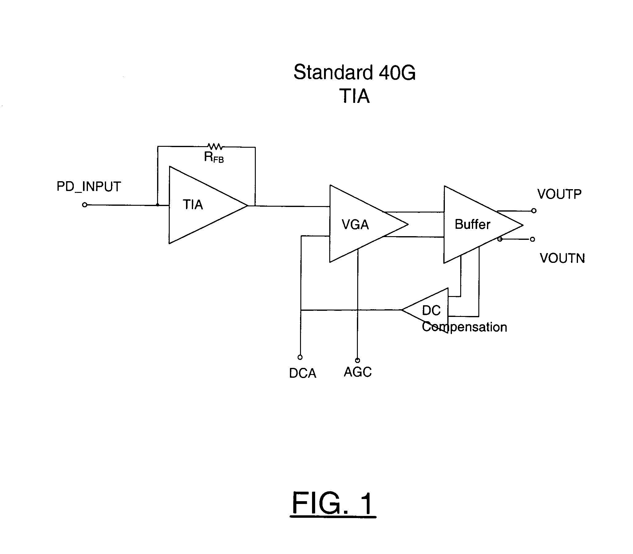
However, because the detection is done near the output, significant distortion of the signal occurs before the automatic gain control loop can effectively reduce the signal to reduce the distortion.
This may lead to residual or multiplicative distortion.
In addition, feedback automatic gain control is not conducive of high performing burst-mode transimpedance amplifier operation due to the delay in the feedback signal.
When implementing a design in silicon technologies, the first stage is usually a differential amplifier due to the lack of backside vias or good single-ended grounds.

Method used


Image

  • Linear multi-stage transimpedance amplifier
  • Linear multi-stage transimpedance amplifier
  • Linear multi-stage transimpedance amplifier

Examples


Embodiment Construction

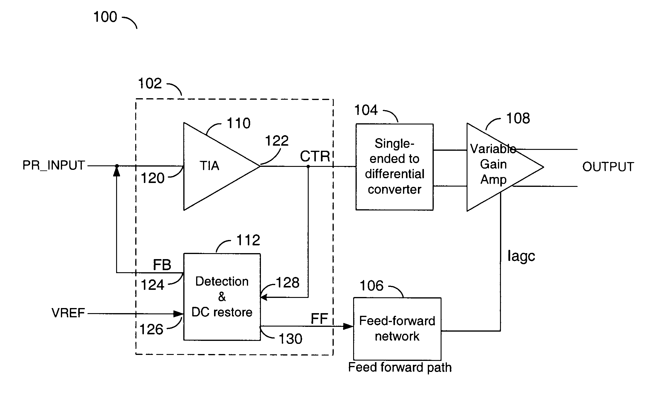
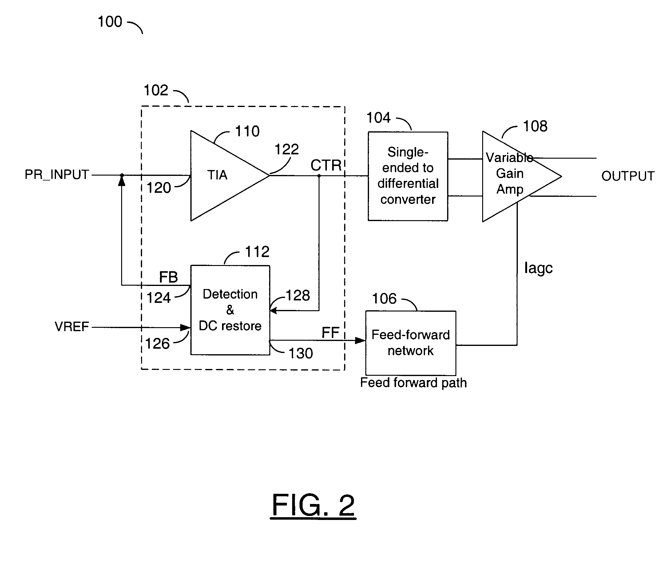
[0022]The present invention provides detection and adjustment in a transimpedance amplifier application early in the signal path. The signal detection is normally provided just after a preamplifier stage, and is fed forward towards a successive stage. The feed-forward may provide gain reduction when a large signal is present. With such a configuration, gain control leveling is done earlier without feedback. Such a configuration may be desirable for burst-mode implementation and may enable greater product applicability.

[0023]The present invention may provide a number of improvements over existing approaches. DC compensation may be accomplished by detecting a signal at the transimpedance amplifier (TIA) preamplifier output, then splitting and feeding forward an average DC level of equal amplitude to both sides of the successive VGA amplifier stage. In one example, DC restore feedback and feed-forward gain control signals may be simultaneously generated from a detection circuit. The de...


PUM


Abstract

An apparatus comprising a first amplifier circuit, a detect circuit, a control circuit and a second amplifier circuit. The first amplifier circuit may be configured to generate an amplified signal in response to an input signal. The detect circuit may be configured to generate a feed-forward signal in response to the amplified signal. The control circuit may be configured to generate a dynamic control signal in response to the feed-forward signal. The second amplifier circuit may be configured to generate an output signal in response to (i) the amplified signal and (ii) the dynamic control signal. The control circuit may be configured to control a gain of the second amplifier circuit by adjusting a magnitude of the dynamic control signal.

Description

FIELD OF THE INVENTION[0001]The present invention relates to amplifiers generally and, more particularly, to a method and / or apparatus for implementing a linear multi-stage transimpedance amplifier.BACKGROUND OF THE INVENTION[0002]As fiber optic data transmission speeds increase, higher linearity will be needed from physical media dependent (PMD) Integrated Circuits (ICs) such as transimpedance amplifiers, modulators and / or laser drivers. In particular, higher linearity transimpedance amplifiers will be needed to support higher order modulation schemes such as differential phase-shift keying (DPSK) or binary phase-shift keying (BPSK), electronic dispersion compensation (EDC), and burst mode data transmission systems.[0003]One conventional solution for implementing a wide dynamic range transimpedance amplifier uses a DC restore topology for linearizing a single-ended pre-amplifier stage of a multi-stage transimpedance amplifier. In addition, the transimpedance amplifier offset correc...

Claims


Application Information

Patent Timeline
IPC IPC(8): H03F3/08
CPCH03F1/083H03F1/32H03F3/087H03G3/3084H03F3/45484H03F3/45085H03F2203/45392H03F2203/45652
Inventor KOBAYASHI, KEVIN W.
Owner QORVO US INC
Why Eureka
Eureka Blog
Learn More