Controller and control method for DC-DC converter

a control method and converter technology, applied in the direction of electric variable regulation, process and machine control, instruments, etc., can solve the problems of linear regulator power loss and inability to achieve satisfactory conversion efficiency, and achieve the effect of higher efficiency

Active Publication Date: 2009-10-27
CYPRESS SEMICON CORP
View PDF16 Cites 54 Cited by
  • Summary
  • Abstract
  • Description
  • Claims
  • Application Information

AI Technical Summary

Benefits of technology

[0011]The power loss of the switching regulator is not affected much by the voltage difference between the input voltage and the output voltage. However, the power loss of the linear regulator is determined by the voltage difference between the input voltage and the output voltage. When the voltage difference between the input voltage and the output voltage is small, the efficiency of the regulator is high as indicated by the double-dashed line in FIG. 2. When the voltage difference is large, the efficiency of the regulator is low as indicated by the single-dashed line in FIG. 2. Thus, when the DC-DC converter is set to switch between the switching regulator and the linear regulator at the load current I1 as shown in FIG. 4, satisfactory conversion efficiency may not be obtained. Further, the voltage difference obtained when the DC-DC converter is set may differ from the voltage difference obtained when the DC-DC converter is actually used. In this case, the efficiency of the DC-DC converter before switching at the load current I1 may differ greatly from the efficiency of the DC-DC converter after switching at the load current I1 as shown in FIGS. 5 and 6. More specifically, when the voltage difference between the input voltage and the output voltage is small, the DC-DC converter is not used as the linear regulator although the efficiency of the linear regulator is higher than the efficiency of the switching regulator as shown in FIG. 5. When the voltage difference between the input voltage and the output voltage is large, the DC-DC converter is used as the linear regulator although the efficiency of the switching regulator is higher than the efficiency of the linear regulator as shown in FIG. 6. In this way, the conversion efficiency of the DC-DC converter may be lowered when the input voltage changes.
[0012]The present invention provides a DC-DC converter, a controller for a DC-DC converter, and a method for controlling a DC-DC converter having conversion efficiency that is not lowered when the input voltage changes.
[0013]One aspect of the present invention is a DC-DC converter including a switching regulator for generating output voltage from input voltage and controlling the output voltage to be constant. A linear regulator generates the output voltage from the input voltage and controls the output voltage to be constant. A controller operates either one of the switching regulator and the linear regulator. The controller monitors the input voltage, the output voltage, and output current, in which the output current changes in accordance with the output voltage. The controller selects the one of the switching regulator and the linear regulator having higher efficiency in accordance with the output current based on the monitoring result.

Problems solved by technology

However, the power loss of the linear regulator is determined by the voltage difference between the input voltage and the output voltage.
Thus, when the DC-DC converter is set to switch between the switching regulator and the linear regulator at the load current I1 as shown in FIG. 4, satisfactory conversion efficiency may not be obtained.

Method used


Image

  • Controller and control method for DC-DC converter
  • Controller and control method for DC-DC converter
  • Controller and control method for DC-DC converter

Examples


first embodiment

[0032]A DC-DC converter 12 according to the present invention will now be described with reference to the drawings.

[0033]FIG. 10 is a schematic block diagram of an electronics device 10 including the DC-DC converter 12. The electronics device 10 is portable, and is driven using power supplied from its built-in battery 11. The battery 11 is connected to the DC-DC converter 12 as a power supply circuit. The DC-DC converter 12 is connected to an internal circuit 13, such as a CPU. The DC-DC converter 12 converts an input voltage Vin supplied from the battery 11 to an output voltage Vout, which is a constant voltage for operating the internal circuit 13. The DC-DC converter 12 supplies the output voltage Vout to the internal circuit 13.

[0034]The configuration of the DC-DC converter 12 will now be described.

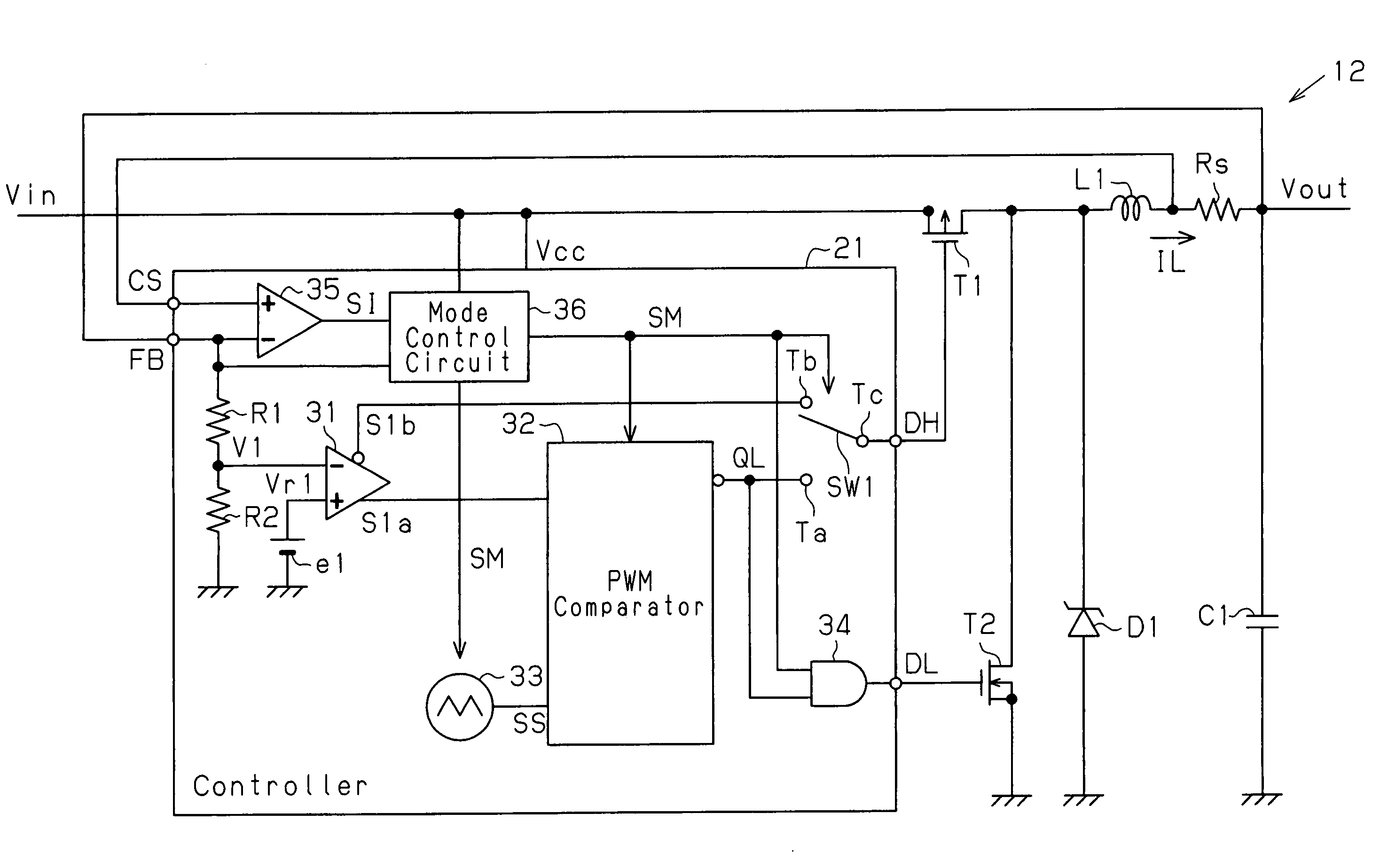
[0035]Referring to FIG. 7, the DC-DC converter 12, which is a voltage control mode DC-DC converter, includes a controller 21, a first output transistor T1, a second output transistor ...

second embodiment

[0120]A DC-DC converter 70 according to the present invention will now be described with reference to the drawing.

[0121]FIG. 13 is a schematic block diagram of the DC-DC converter 70 in the second embodiment. The DC-DC converter 70, which is a current control mode DC-DC converter, includes a controller 71, output transistors T1 and T2, a choke coil L1, a smoothing capacitor C1, a diode D1, and a current detection resistor Rs. Output voltage Vout is output via the current detection resistor Rs.

[0122]In the controller 71, a voltage amplifier 35 has a non-inverting input terminal provided with a feedback signal CS and an inverting input terminal provided with a feedback signal FB. The voltage amplifier 35 amplifies the voltage produced between the two terminals of the current detection resistor Rs based on the output current flowing through the current detection resistor Rs to provide a mode control circuit 36 and a comparator 73 with an amplified signal SI. An error amplifier 31 of th...


PUM


Abstract

A DC-DC converter having conversion efficiency that is not lowered by input voltage change. A mode control circuit of the DC-DC converter monitors the input voltage, output voltage generated from the input voltage, and output current. The output current changes in accordance with the output voltage. Based on the input voltage, output voltage, and consumption current of a controller of the DC-DC converter, the mode control circuit generates a signal that is in accordance with load current in which efficiency of a switching regulator and efficiency of a linear regulator are substantially the same. The mode control circuit further compares a signal corresponding to the output current and the signal that is in accordance with the load current to generate a mode control signal. The controller operates the DC-DC converter as the switching regulator or the linear regulator in accordance with the mode control signal.

Description

CROSS-REFERENCE TO RELATED APPLICATIONS[0001]This application is based upon and claims the benefit of priority from the prior Japanese Patent Application No.2005-263007, filed on Sep. 9, 2005, the entire contents of which are incorporated herein by reference.BACKGROUND OF THE INVENTION[0002]The present invention relates to a DC-DC converter, and more particularly, to a controller and a control method for a DC-DC converter.[0003]Many portable electronics devices are being used in recent years. A portable device uses a battery as a drive power supply. The output voltage of the battery decreases as the device is used or as the battery is discharged. An electronics device includes a DC-DC converter for converting the voltage of its battery to a constant voltage. The conversion efficiency of the DC-DC converter affects the operation time of the electronics device that is operated by the battery. The operation of the electronics device may require a different amount of current. In view of...

Claims


Application Information

Patent Timeline
Patent Type & Authority Patents(United States)
IPC IPC(8): G05F1/40
CPCH02M3/1588Y02B70/1466H02M2001/0045H02M1/0045Y02B70/10H02M3/155
Inventor HASEGAWA, MORIHITO
Owner CYPRESS SEMICON CORP
Why Eureka
Try Eureka