
Magnetic memory and method for reading-writing information from-to magnetic storage element

a magnetic storage element and memory technology, applied in the field of magnetic memory and memory for reading information from to magnetic storage element, can solve the problems of accidental writing, information loss, and inability to provide sufficient power supply in tablets, portable information terminals,

Inactive Publication Date: 2009-11-03
TDK CORPARATION
View PDF25 Cites 2 Cited by
  • Summary
  • Abstract
  • Description
  • Claims
  • Application Information

AI Technical Summary

Benefits of technology

This approach enables increased read current values even with reduced write currents, enhancing the reliability of read-write operations and reducing power consumption.

Problems solved by technology

Volatile memory such as DRAM (Dynamic Random Access Memory) and SRAM (Static RAM) has the disadvantage that information is lost when power failure occurs.
In particular, sufficient power supply cannot always be provided in tablets, portable information terminals, and the like which are intended to be carried on a daily basis.
This is because when the margin is too small, even the read current may cause accidental writing.
However, since it is difficult to increase the read sensitivity of the magnetic storage element 501, it is difficult to correctly detect the resistance value of the magnetic storage element 501 by applying a weak read current.
Hence, there is a limit to the reduction in current consumption.

Method used


Image

  • Magnetic memory and method for reading-writing information from-to magnetic storage element
  • Magnetic memory and method for reading-writing information from-to magnetic storage element
  • Magnetic memory and method for reading-writing information from-to magnetic storage element

Examples


first embodiment

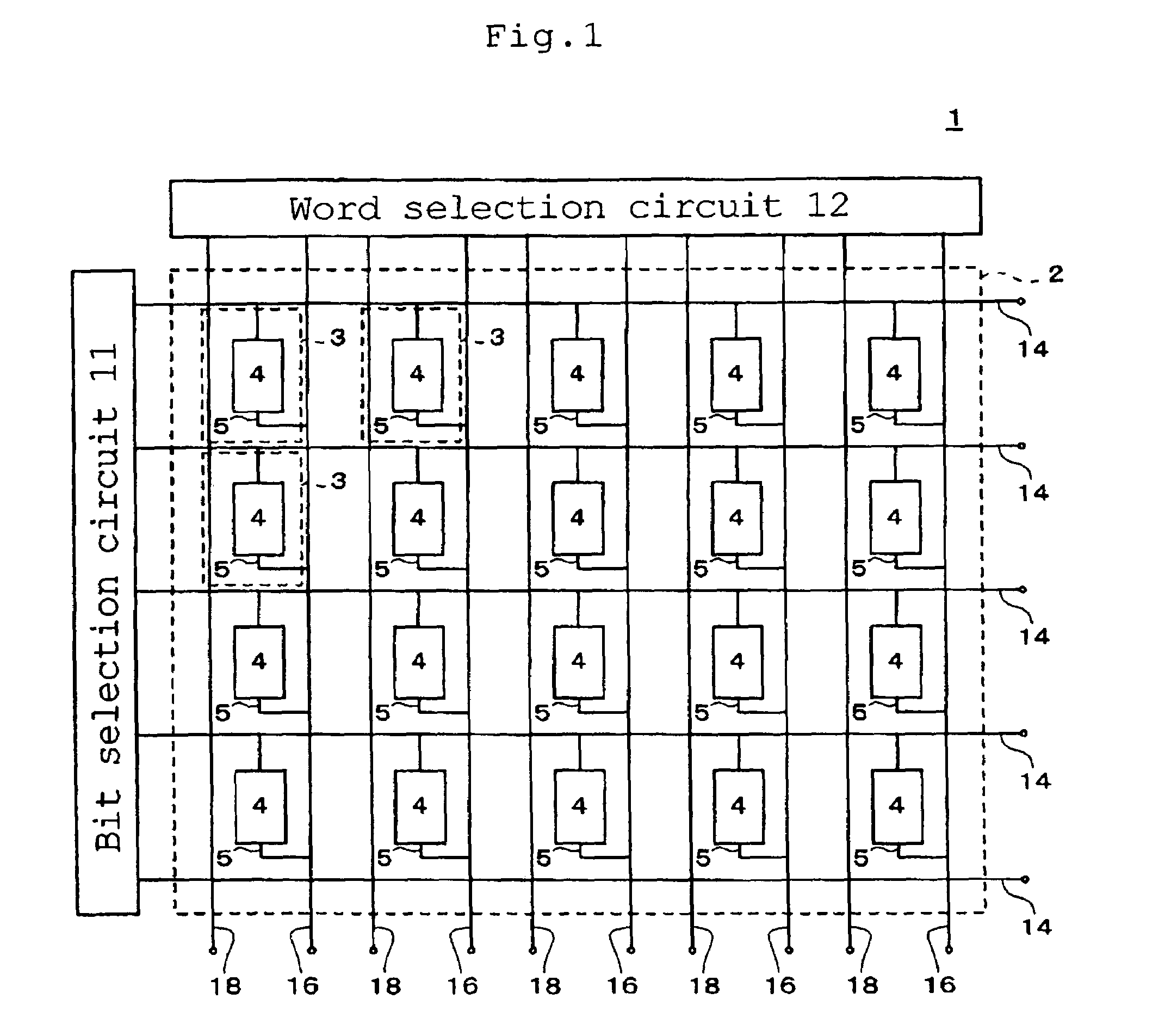
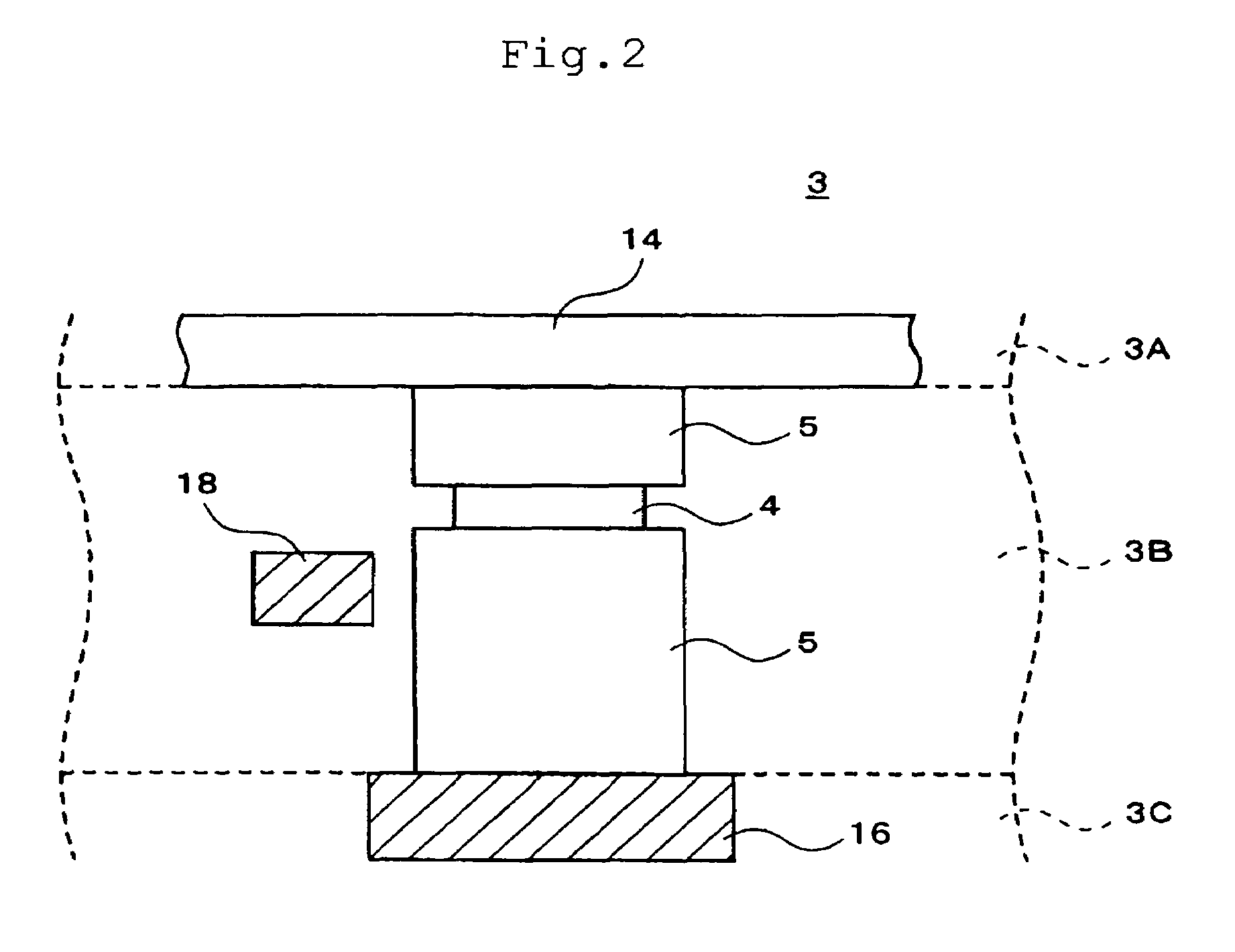
[0043]FIG. 1 is a conceptual diagram showing the overall configuration of a magnetic memory 1 according to the present invention. The magnetic memory 1 includes a storage unit 2, a bit selection circuit 11, a word selection circuit 12, bit lines 14, word lines 16, and bias lines 18. The storage unit 2 has a plurality of storage areas 3 which are arranged in a two-dimensional array with m rows and n columns (m and n are each an integer of 2 or more). Each of the storage areas 3 has a magnetic storage element 4 and a read-write line 5. The read-write line 5 is disposed so as to connect one of the bit lines 14 with a corresponding one of the word lines 16, and the magnetic storage element 4 is provided at some midpoint of the read-write line 5. Specifically, the read-write line 5 is drawn from the bit line 14 and connected to one end of the magnetic storage element 4. The read-write line 5 is also drawn from the word line 16 and connected to the other end of the magnetic storage elemen...

second embodiment

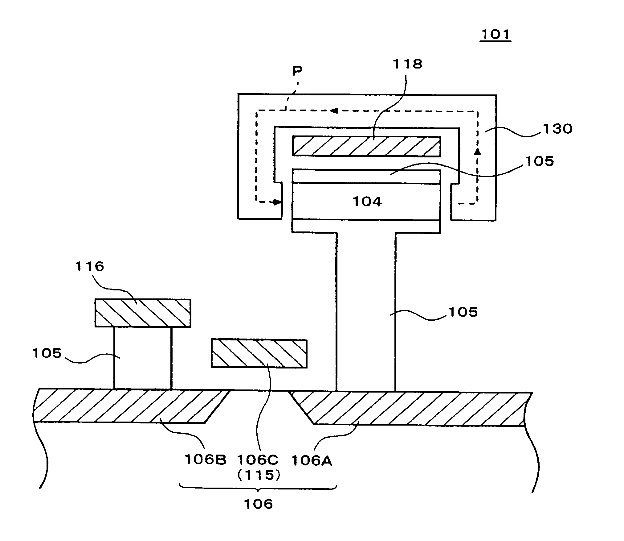
[0075]In the magnetic memory 101 of the second embodiment, the electrical conduction of the current flowing through the read-write line 105 can be structurally controlled by the transistor 106. Therefore, a sneak current and the like can be avoided, so that the read-write precision can be improved. Moreover, since the yoke 130 is formed around the bias line 118, a sufficient bias magnetic field P can be obtained even when the bias current applied to the bias line 118 is reduced. Hence, the current consumption during a reading operation can be reduced.

[0076]Although the description has been given of the magnetic memories of the first and second embodiments, the present invention is not limited to these embodiments, and various modifications can be made thereto. In the above embodiments, the TMR element is employed as a magnetic storage element. However, for example, a GMR (Giant Magneto-resistive) element may be used which utilizes a GMR effect. The GMR effect refers to a phenomenon ...


PUM


Abstract

A magnetic memory is provided in which the margin between a write current and a read current can be reduced. A magnetic storage element includes: a first magnetic layer in which the direction of magnetization can be reversed; a second magnetic layer in which the direction of magnetization is fixed; and a non-magnetic layer which is interposed between the first and second magnetic layers. The write current and the read current are supplied to the magnetic storage element in the stacking direction thereof through a read-write line. Moreover, a bias line which can apply a bias magnetic field to the first magnetic layer during a reading operation is disposed in the vicinity of the magnetic storage element.

Description

BACKGROUND OF THE INVENTION[0001]1. Field of the Invention[0002]The present invention relates to a magnetic memory from and / or to which information is read and / or written using magnetism, and in particular, to an information reading-writing technology suitable for reversing magnetization utilizing electron spins.[0003]2. Description of the Related Art[0004]In recent years, MRAM (Magnetic Random Access Memory) has been receiving attention as a storage device for use in information processing devices such as computers and communication devices. With MRAM, data is stored magnetically, and the direction of magnetization can be maintained without using any electrical means. Volatile memory such as DRAM (Dynamic Random Access Memory) and SRAM (Static RAM) has the disadvantage that information is lost when power failure occurs. However, such a disadvantage can be avoided with MRAM. Furthermore, when compared with conventional non-volatile storage means such as flash EEPROM and hard disk de...

Claims


Application Information

Patent Timeline
Patent Type & Authority Patents(United States)
IPC IPC(8): G11C11/00
CPCG11C11/16G11C11/1673
Inventor TAGAMI, KATSUMICHIHOSOBUCHI, TOSHIKAZU
Owner TDK CORPARATION
Learn More