Hot embossing lithography method

a lithography and hot embossing technology, applied in the field of lithography methods, can solve the problems of reducing the precision of the pattern on the polymer thin film or even destroying the pattern, difficult to form an additional thin layer on the press surface, if even possible, and difficult to maintain the precise depth or width of the relief features. , to achieve the effect of softening the polymer thin film and lowering the surface adsorption energy

Inactive Publication Date: 2009-12-01
HON HAI PRECISION IND CO LTD
View PDF8 Cites 16 Cited by
  • Summary
  • Abstract
  • Description
  • Claims
  • Application Information

AI Technical Summary

Benefits of technology

[0015]introducing a vapor to moisten the press surface of the press mold for lowering a surface adsorption energy of the press surface of the press mold;
[0016]heating the polymer thin film to a temperature above a glass transition temperature of the polymer thin film, therefore softening the polymer thin film;
[0029]Compared with a conventional method, the hot embossing lithography method of any of the described embodiments has the following advantages. Firstly, a surface absorption energy of the press mold is lowered, allowing the press mold to easily separate from the polymer thin film. Secondly, the vapor used in the method is inexpensive. Thirdly, the method ensures precise transformation of the pattern on the press mold to the polymer thin film without damage to the polymer thin film.

Problems solved by technology

These phenomena will damage the pattern formed on the polymer thin film and, therefore, reduce a precision of the pattern on the polymer thin film or even destroy the pattern.
Therefore, it is difficult to form an additional thin layer on the press surface, if even possible.
Likewise, it is difficult to maintain a precise depth or width of the relief features on the press surface due to the additional thin layer.
Furthermore, the surface treated layer is liable to release from the press surface during operation.
Therefore, this solution is hard to practice, and the cost is expensive.

Method used


Image

  • Hot embossing lithography method
  • Hot embossing lithography method
  • Hot embossing lithography method

Examples


Embodiment Construction

[0042]Reference will now be made to the drawings to describe preferred embodiments of the present hot embossing lithography method, in detail.

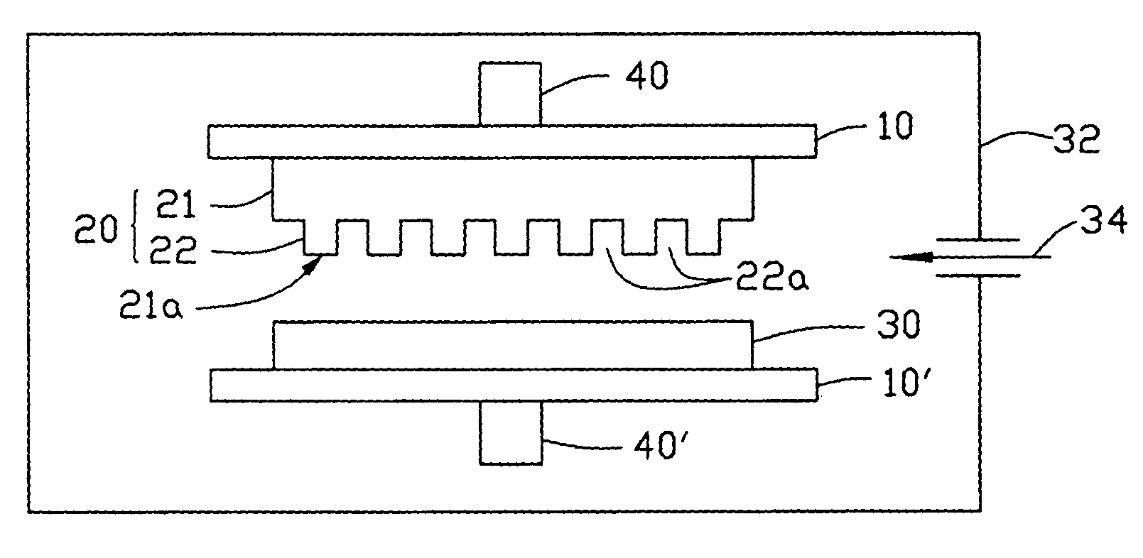
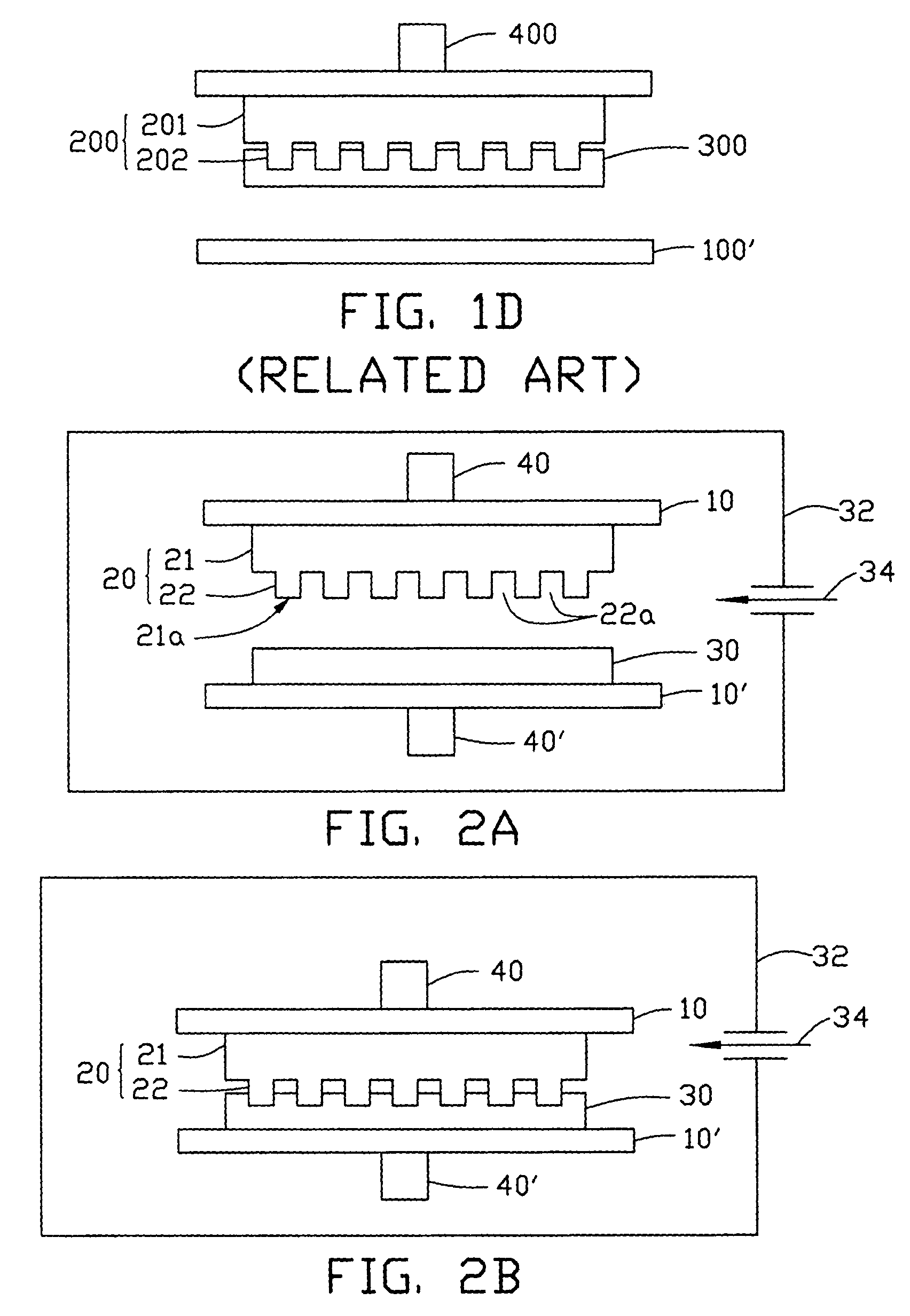
[0043]Referring to FIGS. 2A to 2D, a hot embossing lithography method according to a first preferred embodiment is shown. First, a press mold 20 and a substrate 10′ having a polymer thin film 30 formed thereon are provided. The press mold 20 includes a main body 21 and a press surface 21a. The press surface 21a defines a pattern containing a number of relief structures 22 having a desired shape. Every two neighboring relief structures 22 define a recess 22a therebetween. Generally, the relief structures 22 and the recesses 22a each have a lateral size of about 100 nanometers or less, preferably less than 25 nanometers.

[0044]The polymer thin film 30 can be deposited or coated on the substrate 10′ by any appropriate method, for example, spin coating. Preferably, the polymer thin film 30 includes a thermoplastic polymer, such as polymethyl methac...


PUM

PropertyMeasurementUnit
temperatureaaaaaaaaaa
glass transition temperatureaaaaaaaaaa
pressureaaaaaaaaaa

Abstract

A hot embossing lithography method includes the steps of: providing a press mold (20) having a press surface, the press surface having a pattern defined therein; providing a substrate (10′) having a polymer thin film (30) formed thereon; aligning the press mold with the polymer thin film; introducing a vapor to moisten the press surface for lowering a surface adsorption energy of the press surface; heating the polymer thin film to a temperature above a glass transition temperature of the polymer thin film, thereby softening the polymer thin film; pressing the press mold into the softened polymer thin film to transfer the pattern of the press mold into the polymer thin film; cooling the polymer thin film and the press mold to a temperature near the glass transition temperature of the polymer thin film; and separating the press mold from the polymer thin film.

Description

BACKGROUND OF THE INVENTION[0001]1. Field of the Invention[0002]The invention relates generally to lithography methods for fabrication integrated circuits and micro-devices and, more particularly, to nanoimprint lithography methods for forming, e.g., integrated circuits or ultra fine nanostructures on polymer thin films carried on a substrate.[0003]2. Discussion of the Related Art[0004]Nanoimprint lithography methods are newly developed lithography methods for fabrication of nanostructures with high-resolution, high-throughput and low-cost. The methods are based on an excellent replication fidelity obtained with polymers and combines thermo-plastic molding with common pattern transfer methods. Once a solid stamp (press mold) with a nanorelief on a surface thereof is fabricated, the solid stamp can be used for replication of many identical surface patterns. Therefore, the nanoimprint lithography methods can eliminate many limitations imposed upon conventional optical lithography, suc...

Claims


Application Information

Patent Timeline
Patent Type & Authority Patents(United States)
IPC IPC(8): B28B3/00B28B17/00H01L25/00
CPCB82Y10/00G03F7/0002B82Y40/00Y10S977/887
Inventor YU, TAI-CHERNG
Owner HON HAI PRECISION IND CO LTD
Why Eureka
Try Eureka