Methods and configurations for acid gas enrichment

a technology of acid gas and configuration, applied in the field of gas processing and sulfur removal, can solve the problems of reducing the residence time in the claus furnace, difficult sulfur conversion, and claus plant, and achieve the effects of reducing equipment size and solvent circulation, and increasing hydrogen sulfide concentration

Active Publication Date: 2009-12-22
FLUOR ENTERPRISES
View PDF12 Cites 155 Cited by
  • Summary
  • Abstract
  • Description
  • Claims
  • Application Information

AI Technical Summary

Benefits of technology

[0013]More specifically, the inventors have discovered that use of a second absorber that receives a portion of the isolated hydrogen sulfide, and optionally recycling of the semi-rich amine from the first absorber to the second absorber significantly increases hydrogen sulfide concentration in the isolated hydrogen sulfide. Viewed from another perspective, additional removal of carbon dioxide from the portion of the isolated hydrogen sulfide in a second absorber (and optionally from the Claus tail gas in a third absorber) will concentrate the hydrogen sulfide relative to the carbon dioxide, and thus reduce equipment size and solvent circulation.

Problems solved by technology

However, nearly all gas streams that contain hydrogen sulfide also contain significant quantities of carbon dioxide, and when such gases are scrubbed with an alkaline solution, carbon dioxide is co-absorbed with the hydrogen sulfide.
Co-absorption is particularly problematic where the ratio of carbon dioxide to hydrogen sulfide in the gas stream is relatively high, as such removal will often produce an acid gas with a relatively low concentration of hydrogen sulfide, which tends to cause various problems in the Claus plant.
Among other things, dilution of hydrogen sulfide with relatively large quantities of carbon dioxide lowers the net heating value in the acid gas, thereby reducing the residence time in the Claus furnace, which in turn renders sulfur conversion difficult.
Moreover, such acid gases typically contain significant quantities of contaminants (e.g., benzene, toluene, xylene and heavy hydrocarbons) that must be destroyed in the Claus furnace to protect the downstream Claus reactor catalyst.
However, relatively high carbon dioxide concentrations tend to lower the furnace flame temperature, thereby often making thermal destruction of these contaminants difficult.
Moreover, a relatively high carbon dioxide concentration increases the size of Claus plant components as the configuration of a Claus plant is predominantly controlled by the total volumetric flow of acid gas.
In some cases, where the hydrogen sulfide content in the acid gas is below 10%, the Claus process often becomes ineffective and additional and costly processing steps must be employed to enhance the conversion (e.g., using an oxygen or oxygen enriched process).
Where the acid gas is entirely unsuitable as a feed to a Claus plant, preprocessing using a selective acid gas removal process is frequently necessary.
However, these units are often complex, difficult to operate, and limited to relatively small capacity.
Unfortunately, the use of such processes and / or devices in most cases is not effective and produces only insignificant economic benefit for treating a diluted acid gas stream.
While this configuration will marginally increase the concentration of hydrogen sulfide in the resultant acid gas, mixing of two different gases (i.e., the feed gas and the recycled acid gas) having varying hydrogen sulfide concentrations will typically result in a loss of efficiency.
Moreover, the use of a single absorber in treating the combined gas requires a high solvent circulation, adding to the cost-ineffectiveness of such configurations.
However, such systems are often costly to install and complicated to operate.
However, the cost and complexity of operating a refrigeration unit renders such an option often uneconomical.
Even where selective acid gas absorption using concurrent conversion of hydrogen sulfide to elemental sulfur in a Claus plant is employed, residual sulfur content in the Claus plant tail gas often poses additional problems.
Among other things, the Claus plant tail gas frequently contains substantial quantities of hydrogen sulfide and therefore fails to meet the environmental emission standards for discharging into the atmosphere.
However, most the known configurations are relatively complex and expensive to operate.
Therefore, and especially where a diluted acid gas feed is encountered, currently known methods and configurations are often neither suitable nor economical.

Method used


Image

  • Methods and configurations for acid gas enrichment
  • Methods and configurations for acid gas enrichment
  • Methods and configurations for acid gas enrichment

Examples


Embodiment Construction

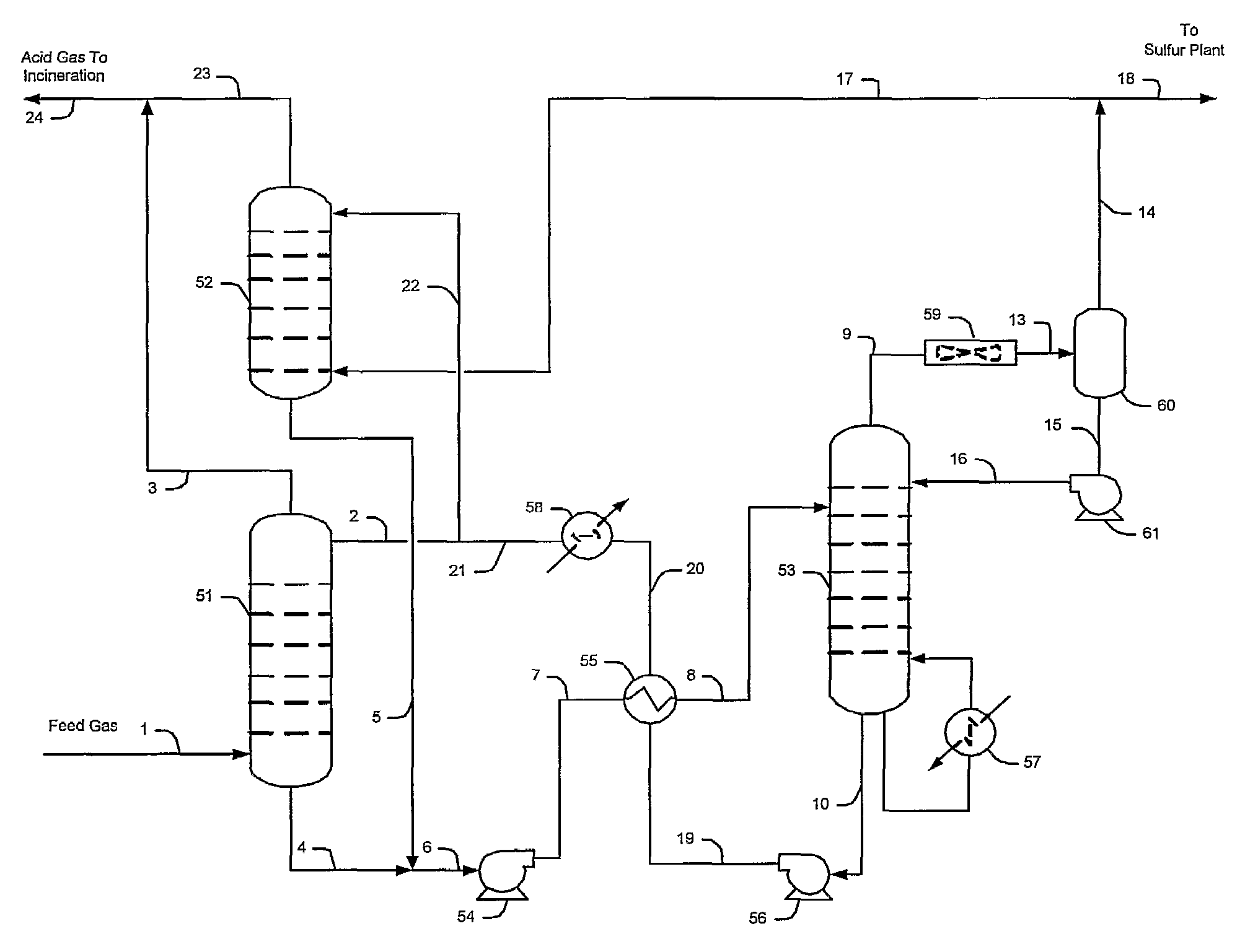
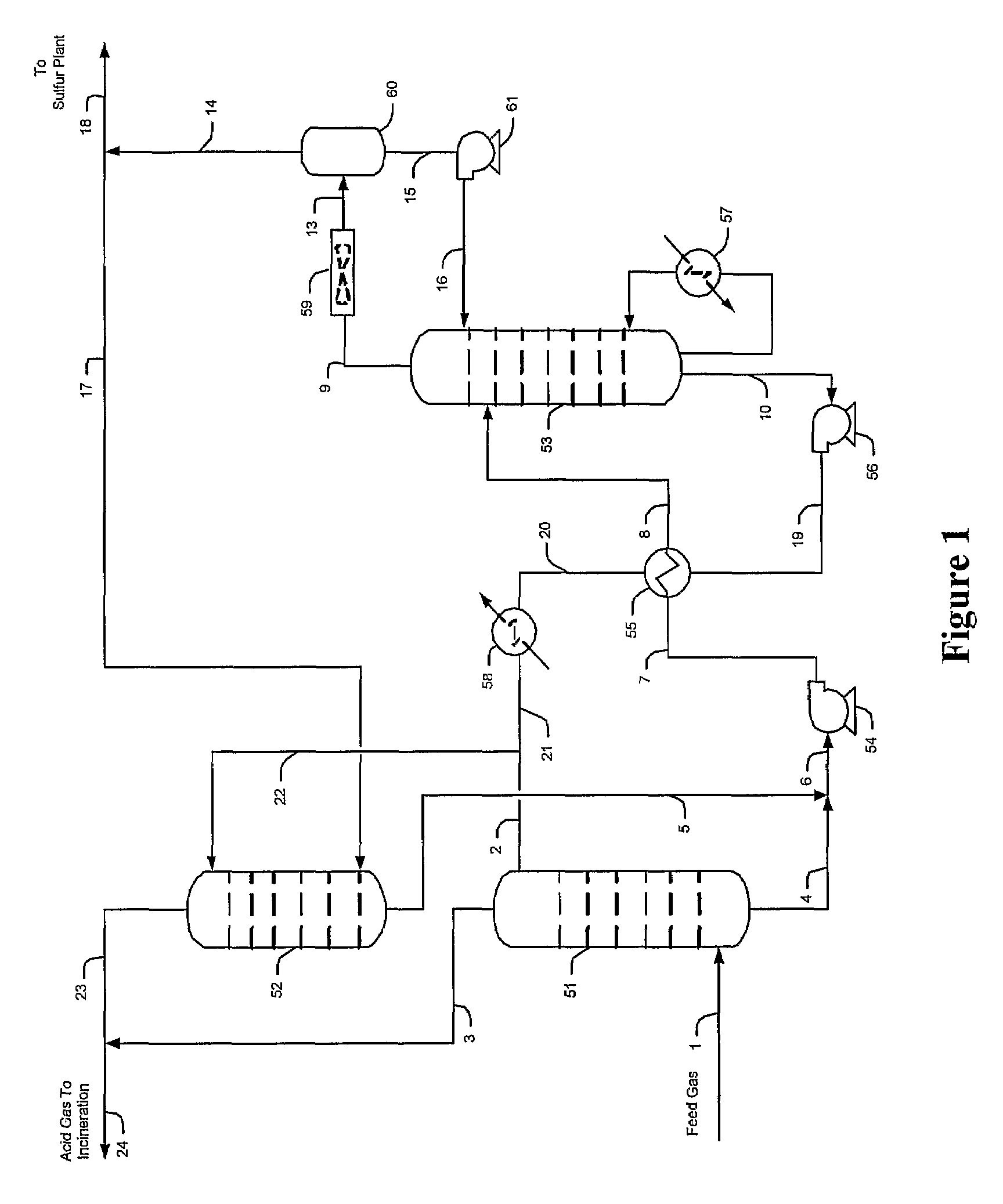
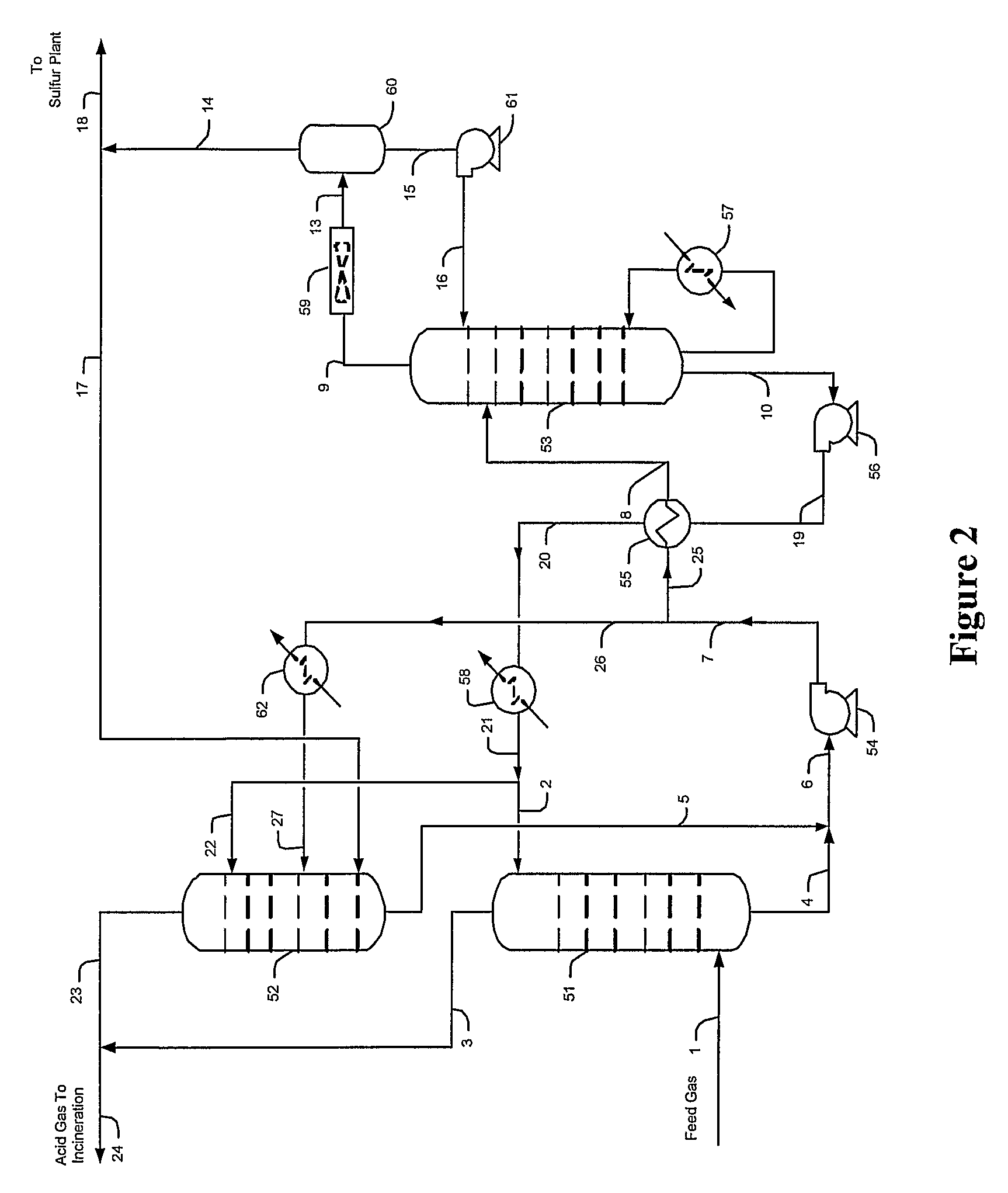
[0029]The inventors generally contemplate configurations and methods of selective hydrogen sulfide absorption and sulfur recovery from various gases comprising hydrogen sulfide and carbon dioxide, and especially from gases in which hydrogen sulfide is diluted. Contemplated configurations may also include an integrated sulfur plant (e.g., Claus plant) that receives a portion of an hydrogen sulfide-rich gas and that provides a tail gas to the plant from which the hydrogen sulfide is reabsorbed by a solvent while the carbon dioxide and other contaminants are rejected.

[0030]Most preferably, solvents used in conjunction with the teachings presented herein are selective towards hydrogen sulfide, and most preferably include tertiary amines, activated amines, sterically hindered amines, and / or complex amines. There are numerous such solvents known in the art, and all of the known hydrogen selective solvents are deemed suitable for use herein.

[0031]Contemplated configurations are particularl...


PUM

PropertyMeasurementUnit
outlet temperatureaaaaaaaaaa
concentrationaaaaaaaaaa
pressureaaaaaaaaaa

Abstract

Hydrogen sulfide is selectively enriched from an acid gas (1) that comprises relatively large quantities of carbon dioxide using a configuration in which a portion of an isolated hydrogen sulfide stream is introduced into an absorber (51) operating as a carbon dioxide rejecter. The resulting concentrated hydrogen sulfide enriched solvent (4) is then further used (directly or indirectly) to absorb hydrogen sulfide from an acid feed gas.

Description

[0001]This application claims priority to our commonly owned and copending U.S. provisional patent applications with the Ser. Nos. 60 / 538,105 (filed 20 Jan. 2004), 60 / 538,122 (filed 20 Jan. 2004), 60 / 538,608 (filed 22 Jan. 2004), and 60 / 565,053 (filed 22 Apr. 2004), each of which is incorporated by reference herein.FIELD OF THE INVENTION[0002]The field of the invention is gas processing and sulfur removal, especially as it relates to enrichment of an acid gas stream with high carbon dioxide content and a tail gas from Claus plant.BACKGROUND OF THE INVENTION[0003]There are numerous sources of natural or synthetic gases known in the art, and almost all of them contain hydrogen sulfide in various quantities that require at least partial desulfurization prior to further processing or release into the atmosphere. For example, natural gas, refinery gas, synthesis gas (e.g., from gasification of residual oil or coke), or Fischer-Tropsch gas-to-liquids process gases often contain hydrogen s...

Claims


Application Information

Patent Timeline
Patent Type & Authority Patents(United States)
IPC IPC(8): B01D53/14C01B17/04C01B17/16C01B32/50
CPCB01D53/1406B01D53/1468C10L3/10C01B17/0408C01B17/167B01D2252/20431B01D2256/22
Inventor MAK, JOHNNIELSEN, RICHARD B.CHOW, THOMAS KINGMORGAN, OLIVERWONG, VINCENT WAI
Owner FLUOR ENTERPRISES
Why Eureka
Try Eureka