Isolated bidirectional DC-DC converter

a dc-dc converter and bi-directional technology, applied in the direction of instruments, base element modifications, emergency protective arrangements for limiting excess voltage/current, etc., can solve the problems of enlargement of the apparatus and reduce efficiency, and achieve the effect of miniaturization highly efficient and loss due to the circulating current when buck mode can be reduced

Active Publication Date: 2009-12-29
HITACHI ASTEMO LTD
View PDF14 Cites 40 Cited by
  • Summary
  • Abstract
  • Description
  • Claims
  • Application Information

AI Technical Summary

Benefits of technology

[0007]An object of the present invention is to provide an isolated bidirectional DC-DC converter for suppressing an occurrence of a loss or a surge voltage and realizing efficient miniaturization of the converter.
[0011]According to the preferred embodiments of the present invention, in the two-way insulating DC-DC converter, the loss due to the circulating current when buck mode can be reduced.
[0012]Further, according to the preferred embodiments of the present invention, an isolated bidirectional DC-DC converter which can prevent an occurrence of a surge voltage on the low voltage side in both modes of buck and voltage boost and can be miniaturized highly efficiently can be provided.

Problems solved by technology

In the prior art disclosed in Patent Document 1, when buck mode, a loss due to a circulating current is caused, thus a reduction in efficiency is caused, and when increasing and buck mode, a surge voltage is generated on the low voltage side, and in correspondence to it, it is necessary to increase the breakdown voltage of the switching device, and in either case, enlargement of the apparatus is required.

Method used


Image

  • Isolated bidirectional DC-DC converter
  • Isolated bidirectional DC-DC converter
  • Isolated bidirectional DC-DC converter

Examples


embodiment 1

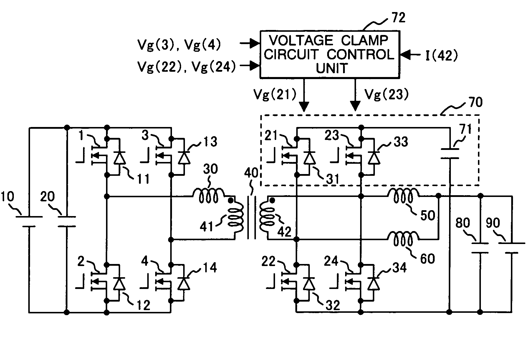
[0026]FIG. 1 is a circuit block diagram of the two-way insulating DC-DC converter of the first embodiment of the present invention. In the drawing, to a DC power source 10 on the high voltage side, a smoothing condenser 20 and a load (not drawn), a first switching arm composed of switching devices 1 and 2 connected in series, and a second switching arm composed of switching devices 3 and 4 connected in series are connected in parallel. To the switching devices 1 to 4, free wheel diodes 11 to 14 are respectively connected in reverse parallel and when the switching devices 1 to 4 are MOSFETs, a body diode can be used. The first and second switching arms are connected to the DC power source 10 in parallel, so that a voltage switching circuit is formed and between the AC terminals of the switching circuit, a primary winding 41 of a transformer 40 is connected via an auxiliary reactor 30. The auxiliary reactor 30, when inverting the polarity of the current flowing through the switching c...

embodiment 2

[0056]FIG. 8 is a circuit block diagram of the two-way insulating DC-DC converter of the second embodiment of the present invention. To the same parts as those shown in FIG. 1, the same numerals are assigned and the explanation will be omitted. In FIG. 8, the difference on the basic circuit from FIG. 1 is that a center tap is installed on the secondary winding 42 of the transformer 40, and the reactor 50 is connected between the center tap and the positive pole of the DC power source 90, and the reactor 60 is removed. By doing this, the voltage clamp circuit 70 is composed of only one series unit of the switching device 23 with the reverse parallel diode 33 and the clamp condenser 71 and the number of parts can be reduced. The switching device 23 is driven by the voltage clamp circuit control unit 74 and is controlled in switching.

[0057]FIG. 9 is a drive voltage waveform diagram of each switching device at the time of buck of the second embodiment of the present invention. In the dr...

embodiment 3

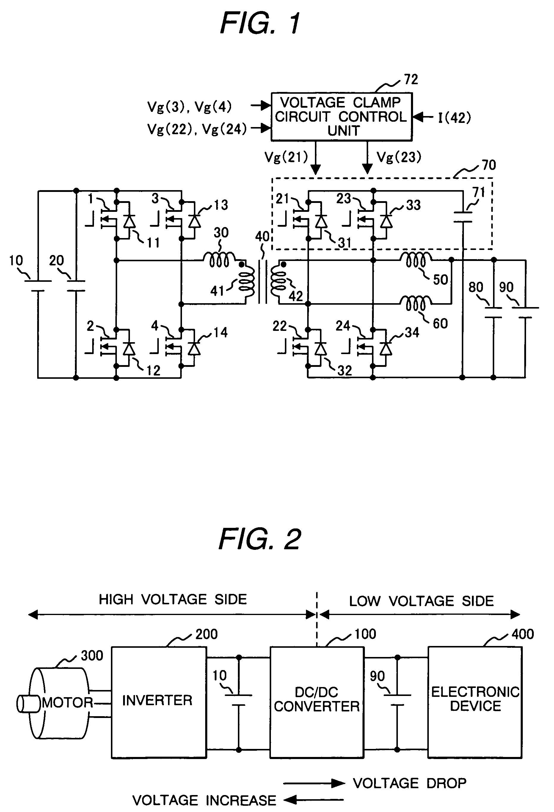
[0065]When the two-way insulating DC-DC converter of the present invention, for example, is used in a power source system for a car, it must be mounted in a limited space, so that a request for miniaturization is increased and a stable operation in a high-temperature environment is required. Therefore, as a converter, miniaturization of the transformer and reactor by realization of high frequency, reduction in the on loss of the switching devices and the number of switching devices, and improvement of the cooling method are required.

[0066]FIG. 11 is a circuit block diagram of the two-way insulating DC-DC converter of the third embodiment of the present invention. The difference from Embodiment 1 shown in FIG. 1 is that a static induction transistor (SIT) and an SiC diode using a silicon carbide (SiC) composition material are used. SiC-SIT, compared with the switching devices using a silicone composition material, has excellent characteristics in both aspects of the on resistance and...


PUM


Abstract

The DC-DC converter connects a first and a second switching circuit for converting power mutually between direct current and alternating current respectively to a first DC power source and a second DC power source and has a transformer between the AC terminals thereof. Here, between the AC terminals of the second switching circuit and the negative pole terminal of the DC power source, a voltage clamp circuit composed of a series unit of switching devices with a reverse parallel diode and a clamp condenser is connected.An isolated bidirectional DC-DC converter which prevents a reduction in a circulating current at time of buck and an occurrence of a surge voltage at time of voltage boost and realizes highly efficiency, low noise, and miniaturization is provided.

Description

CLAIM OF PRIORITY[0001]The present application claims priority from Japanese application Ser. No. 2004-379478, filed on Dec. 28, 2004, the content of which is hereby incorporated by reference into this application.FIELD OF THE INVENTION[0002]The present invention relates to an isolated bidirectional DC-DC converter.BACKGROUND OF THE INVENTION[0003]To transfer power between two DC power sources at different voltages, a two-way DC-DC converter having a buck and boost function between the two power sources is required. For example, a power source system of a hybrid car has batteries on the high voltage side and low voltage side, supplies power to a drive motor via an inverter from the high voltage side battery, and supplies power to a car control electronic device from the low voltage side battery. The two batteries are connected via the DC-DC converter to enable mutual transfer of power and the DC-DC converter performs a buck operation when supplying power from the high voltage side t...

Claims


Application Information

Patent Timeline
Patent Type & Authority Patents(United States)
IPC IPC(8): G01R1/20
CPCH02M1/34H02M3/33584Y02B70/1491H02M2001/342H02M1/342Y02B70/10
Inventor SHOJI, HIROYUKIKANOUDA, AKIHIKOSAITO, RYUICHIYUKUTAKE, SEIGOUHIGUCHI, KATSUHIRO
Owner HITACHI ASTEMO LTD
Why Eureka
Try Eureka