
Liquid crystal panel and liquid crystal display apparatus

a liquid crystal display and liquid crystal technology, applied in non-linear optics, instruments, optics, etc., can solve the problem of difficulty in expressing a neutral display having no color shift in all azimuth angle directions, and achieve the effect of small photoelastic coefficient, decrease in thickness direction retardation, and increase in wavelength

Active Publication Date: 2009-12-29
NITTO DENKO CORP
View PDF7 Cites 52 Cited by
  • Summary
  • Abstract
  • Description
  • Claims
  • Application Information

AI Technical Summary

Benefits of technology

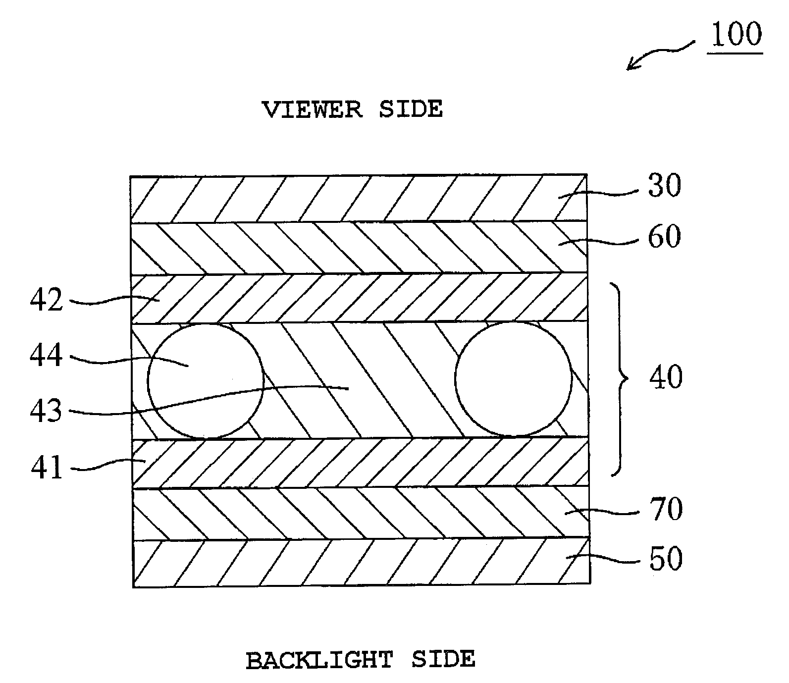
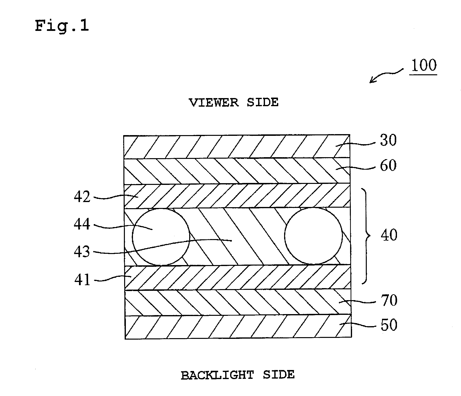
The present invention provides a liquid crystal panel and display apparatus that can produce a neutral display with no color shift in all directions. This is achieved by combining two layers of optical compensation with specific properties. The first layer has a flat wavelength dispersion, small photoelastic coefficient, and refractive index profile, while the second layer has a refractive index profile that decreases with wavelength. This combination of layers also acts as a protective layer on the liquid crystal cell side of one polarizer, contributing to the reduction in thickness of the display apparatus.

Problems solved by technology

However, in a conventional liquid crystal display apparatus, it is difficult to express a neutral display having no color shift in all azimuth angle directions.

Method used


Image

  • Liquid crystal panel and liquid crystal display apparatus
  • Liquid crystal panel and liquid crystal display apparatus
  • Liquid crystal panel and liquid crystal display apparatus

Examples


reference example 1

Production of a Polarizer

May be Referred to as First Polarizer and / or Second Polarizer

[0153]A polyvinyl alcohol film was colored in an aqueous solution containing iodine, and the resultant was uniaxially stretched 6 times between rolls with different speed ratios in an aqueous solution containing boric acid, to thereby produce a polarizer.

reference example 2

Preparation of a Polyvinyl Alcohol-Based Adhesive

[0154]50 parts by weight of methylol melamine were dissolved in pure water at a temperature of 30° C. with respect to 100 parts by weight of a polyvinyl alcohol-based resin containing an acetoacetyl group (“GOSEFIMER Z200” (trade name), manufactured by Nippon Synthetic Chemical Industry Co., Ltd., average polymerization degree: 1,200, saponification degree: 98.5 mol %, acetoacetylation degree: 5 mol %), whereby an aqueous solution with a solid content adjusted to 3.7% was obtained. To 100 parts by weight of the aqueous solution, 18 parts by weight of an aqueous alumina colloidal solution (average particle size: 15 nm, solid content: 10%, positive charge) was added, to thereby prepare an adhesive aqueous solution. The viscosity of the adhesive aqueous solution was 9.6 mPa·s. The pH of the adhesive aqueous solution was 4 to 4.5.

reference example 3

Preparation of a Polyvinyl Alcohol-Based Adhesive

[0155]50 parts by weight of methylol melamine were dissolved in pure water at a temperature of 30° C. with respect to 100 parts by weight of a polyvinyl alcohol-based resin containing an acetoacetyl group (“GOSEFIMER Z200” (trade name), manufactured by Nippon Synthetic Chemical Industry Co., Ltd., average polymerization degree: 1,200, saponification degree: 98.5 mol %, acetoacetylation degree: 5 mol %), whereby an adhesive aqueous solution with a solid content adjusted to 3.7% was obtained. The viscosity of the adhesive aqueous solution was 9.6 mPa·s. The pH of the adhesive aqueous solution was 4 to 4.5.


PUM

PropertyMeasurementUnit
wavelengthaaaaaaaaaa

Abstract

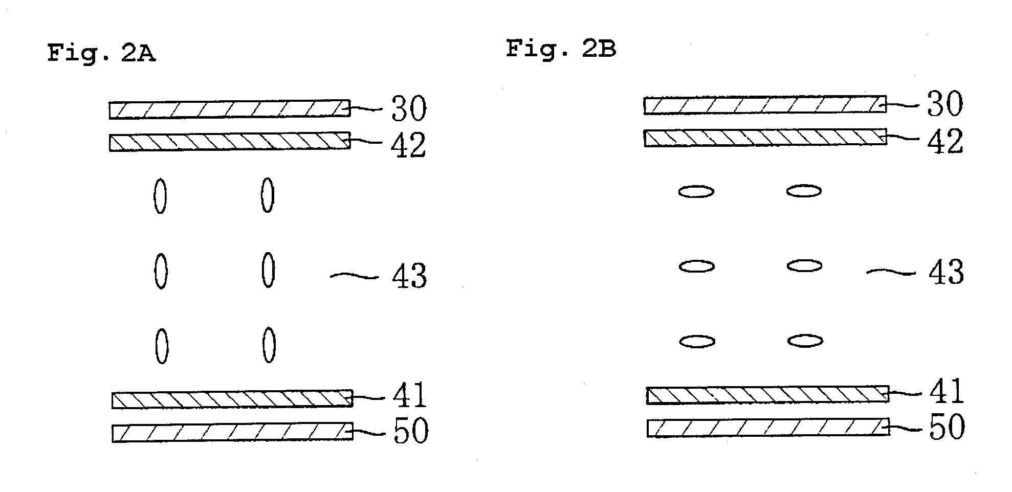
The liquid crystal panel according to an embodiment of the present invention includes, in the stated order from a viewer side: a first polarizer; a first optical compensation layer; a liquid crystal cell; a second optical compensation layer; and a second polarizer, wherein:the first optical compensation layer has an absolute value of a photoelastic coefficient of 40×10−12 (m2 / N) or less, has an in-plane retardation Δnd of 90 nm to 200 nm, has relationships of the following Expressions (1) and (2), and functions as a protective layer on a liquid crystal cell side of the first polarizer; andthe second optical compensation layer has relationships of the following Expressions (3) and (4),Δnd(380)=Δnd(550)=Δnd(780)  (1)nx>ny>nz  (2)Rth(380)>Rth(550)>Rth(780)  (3)nx=ny>nz  (4).

Description

[0001]This application claims priority under 35 U.S.C. Section 119 to Japanese Patent Application No. 2007-120633 filed on May 1, 2007, Japanese Patent Application No. 2007-148256 filed on Jun. 4, 2007, and Japanese Patent Application No. 2007-298072 filed on Nov. 16, 2007, which are herein incorporated by references.BACKGROUND OF THE INVENTION[0002]1. Field of the Invention[0003]The present invention relates to a liquid crystal panel and to a liquid crystal display apparatus. In particular, the present invention relates to a liquid crystal panel suitable for a liquid crystal display apparatus and capable of providing a neutral display having no color shift in all azimuth angle directions, and to a liquid crystal display apparatus using the liquid crystal panel.[0004]2. Description of the Related Art[0005]FIG. 5A is a schematic cross-sectional view of a conventional typical liquid crystal display apparatus, and FIG. 5B is a schematic cross-sectional view of a liquid crystal cell use...

Claims


Application Information

Patent Timeline
Patent Type & Authority Patents(United States)
IPC IPC(8): G02F1/13363
CPCG02F1/133634G02F2413/02G02F2001/133635G02F1/1393G02F1/133635G02F1/1335G02F1/13363
Inventor TAKEDA, KENTAROUKITAGAWA, TAKEHARUHAYASHI, DAISUKEISHIDA, HIDEKIMURAKAMI, NAONAGASE, JUNICHI
Owner NITTO DENKO CORP
Learn More