Gas sealing skirt for suspended showerhead in process chamber

a technology of gas sealing skirt and suspended showerhead, which is applied in the direction of electric discharge tubes, coatings, chemical vapor deposition coatings, etc., can solve the problems of suspension experiencing thermal shock, and achieve the effects of reducing thermal shock, reducing heat transfer rate, and reducing thermal stress

Inactive Publication Date: 2010-01-05
APPLIED MATERIALS INC
View PDF65 Cites 10 Cited by
  • Summary
  • Abstract
  • Description
  • Claims
  • Application Information

AI Technical Summary

Benefits of technology

[0013]One aspect of the invention is a gas sealing skirt for enclosing the sides of the volume (i.e., the gas inlet plenum) through which process gas flows from the gas inlet in the chamber wall to the gas outlets in the showerhead. Because the gas sealing skirt performs this gas enclosure function, the suspension preferably can be positioned outside the volume enclosed by the gas sealing skirt so that the gas sealing skirt protects the suspension from exposure to the process gas.
[0015]A second aspect of the invention is a suspension having one or more suspension walls, each of which includes one or more openings that collectively occupy at least five percent of the area of the suspension wall. The openings reduce thermal stress in the suspension by reducing the area of the suspension wall exposed to gas within the process chamber, thereby reducing the rate of heat transfer between the suspension and such gas.
[0016]The openings are especially advantageous to reduce stress (thermal shock) within the suspension wall when the chamber lid inadvertently is opened to expose the chamber interior to ambient atmosphere without first allowing the chamber components to cool down. The openings reduce the area of the suspension walls exposed to the cool air at ambient atmospheric pressure rushing into the chamber, thereby reducing the rate of cooling of the suspension wall.
[0017]A third aspect of the invention is a suspension having one or more suspension walls, each of which includes a substantially vertical arrangement of one or more rifts in the suspension wall. A substantially vertical arrangement of one or more rifts can be either a single rift that is substantially vertically elongated, or else a plurality of rifts of any shape that are spaced apart in a substantially vertical direction. For the purposes of this patent specification and claims, “substantially vertical” means within 45 degrees of vertical. A rift can be a slit, perforation or opening of any shape that extends entirely through the suspension wall. Alternatively, a rift can be a groove or notch that does not extend entirely through the suspension wall. Advantageously, the rifts can ameliorate stress in a suspension wall by weakening the wall at the location of the rifts, thereby facilitating horizontal flexing or buckling of the wall in response to thermal stress.
[0018]A fourth aspect of the invention comprises replacing at least one of the suspension walls with a plurality of suspension walls whose respective central portions are coplanar. Replacing one suspension wall with two, three or more coplanar suspension walls reduces the width of each suspension wall by approximately two, three or more, respectively, thereby correspondingly reducing the horizontal component of any thermally induced stress in each suspension wall.

Problems solved by technology

Older showerhead designs mounted the showerhead to the wall of the process chamber using relatively thick mounting flanges that kept the showerhead undesirably cool by conducting heat from the showerhead to the relatively cool wall of the process chamber.
Therefore, if the chamber lid is opened when the suspension is hot, the suspension may experience thermal shock as the suspension rapidly cools and contracts while the bottom flange remains stuck to the showerhead.

Method used


Image

  • Gas sealing skirt for suspended showerhead in process chamber
  • Gas sealing skirt for suspended showerhead in process chamber
  • Gas sealing skirt for suspended showerhead in process chamber

Examples


Embodiment Construction

1. Process Chamber Overview

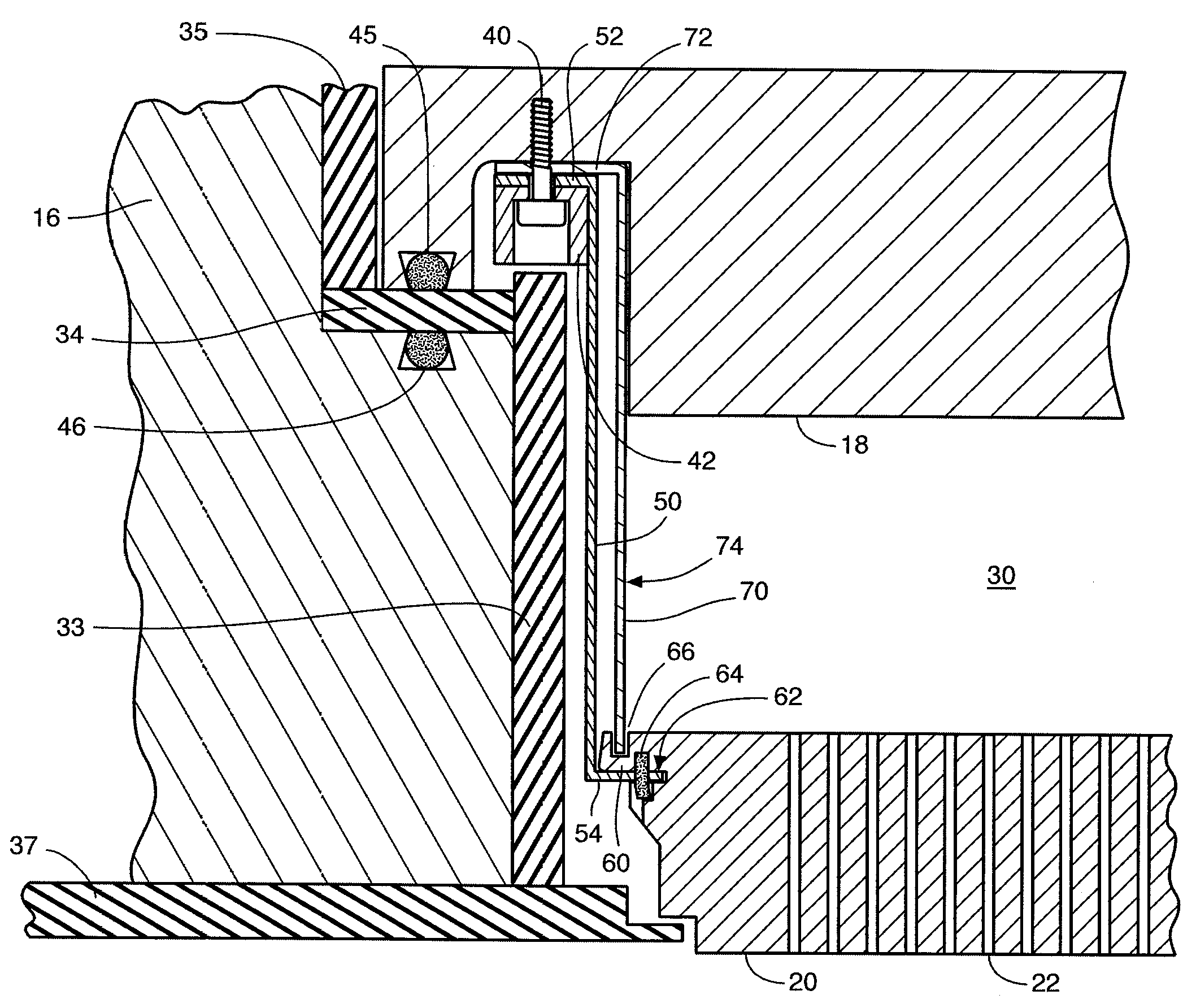
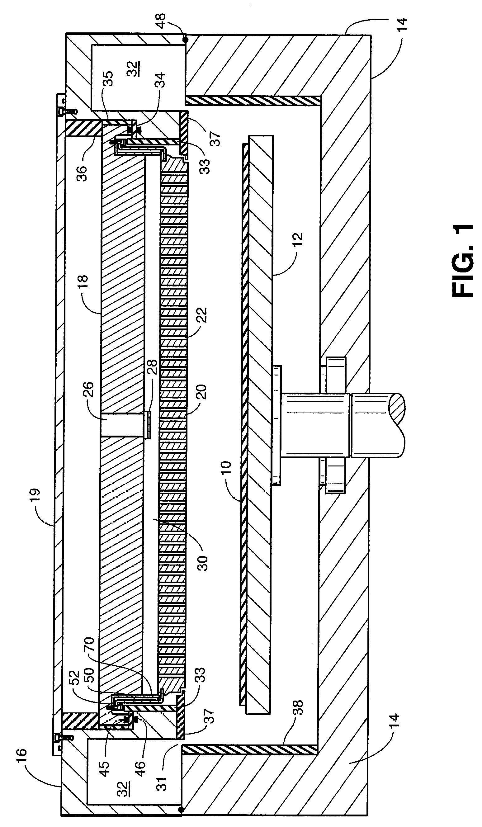
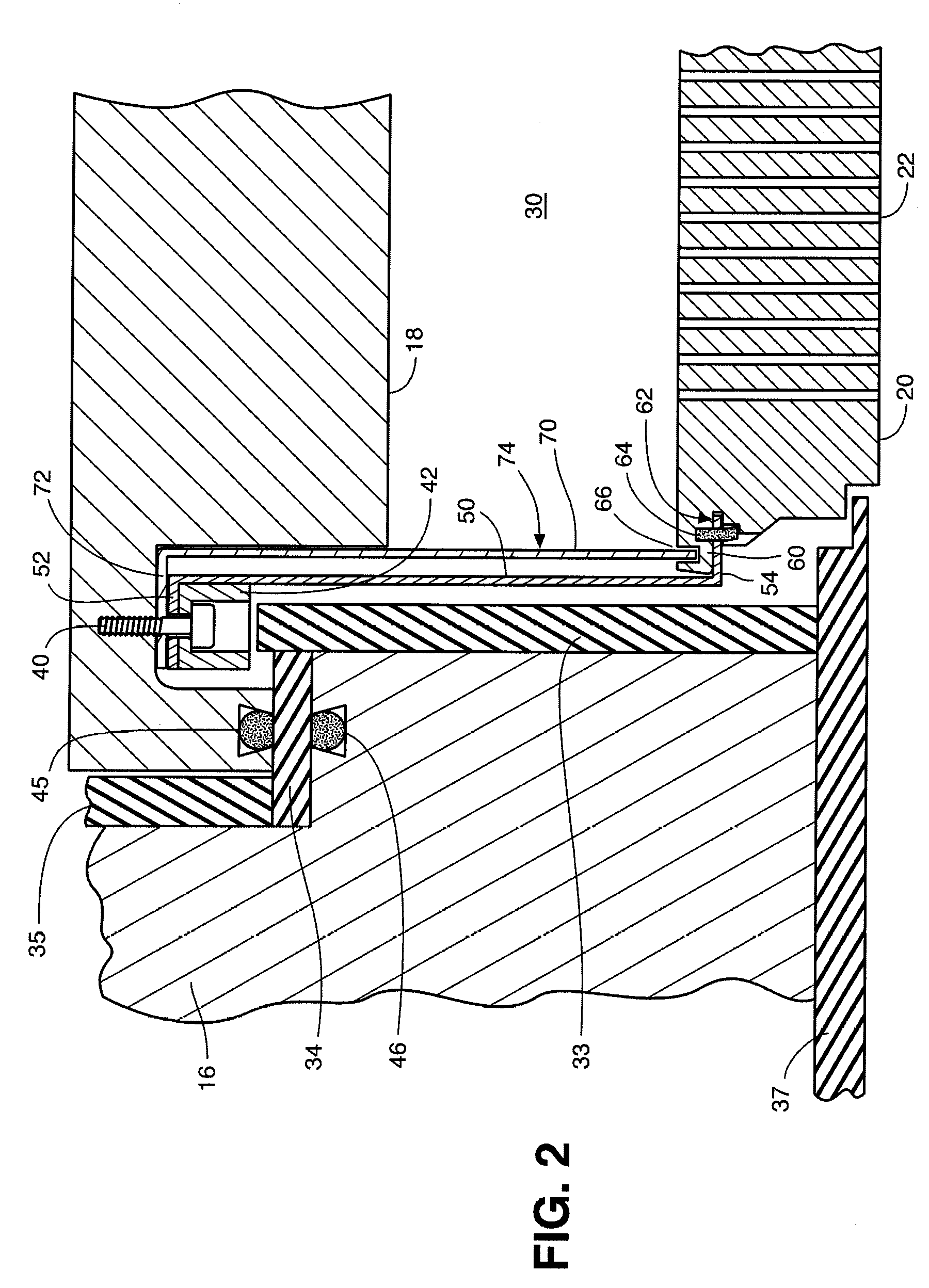
[0032]FIGS. 1 and 2 show a process chamber that includes a suspended showerhead 20 and gas sealing skirt 70 according to the invention. Before describing the invention, the other components of the process chamber will be described.

[0033]The process chamber is a vacuum chamber intended to subject a workpiece or substrate 10 to a chemical process that is one step in a sequence of steps in the fabrication of electronic devices, such as flat panel displays or semiconductors, on the workpiece. The workpiece is supported within the chamber by a workpiece support 12, also called a chuck or susceptor. Common examples of a workpiece 10 that would be processed within the chamber include a rectangular glass substrate on which flat panel displays are fabricated or a circular semiconductor wafer on which integrated circuits are fabricated.

[0034]The process chamber has a housing or chamber wall 14, 16, 18 that provides a vacuum enclosure for the chamber interior. In the...


PUM

PropertyMeasurementUnit
thickaaaaaaaaaa
widthaaaaaaaaaa
widthaaaaaaaaaa

Abstract

Stress within a suspension wall for suspending a showerhead in a process chamber is ameliorated by one or more of: (1) A gas sealing skirt that helps protect the suspension wall from direct contact with process gas. The gas sealing skirt is connected to either the chamber wall or the showerhead but is not connected to both. (2) Openings in the suspension wall that reduce exposure of the suspension wall to process gas or ambient atmosphere when the chamber lid is opened. (3) A substantially vertical arrangement of one or more rifts in the suspension wall which facilitate horizontal buckling or flexing of the suspension wall. (4) A plurality of suspension walls whose respective central portions are coplanar.

Description

[0001]This patent application claims the benefit of U.S. provisional application No. 60 / 713,875 filed Sep. 2, 2005.FIELD OF THE INVENTION[0002]The invention relates to apparatus and methods for suspending a showerhead for dispensing gas into a vacuum chamber used for manufacturing flat panel displays, semiconductors, and other electronic devices. More specifically, the invention relates to a gas sealing skirt for protecting the suspension from exposure to process gas supplied to a gas inlet manifold of a process chamber.BACKGROUND OF THE INVENTION[0003]Electronic devices, such as flat panel displays and integrated circuits, commonly are fabricated by a series of process steps in which layers are deposited on a substrate and the deposited material is etched into desired patterns. The process steps commonly include plasma-enhanced chemical vapor deposition (CVD) processes, thermal (non-plasma) CVD processes, and plasma-enhanced etch processes.[0004]The substrate generally is mounted o...

Claims


Application Information

Patent Timeline
Patent Type & Authority Patents(United States)
IPC IPC(8): C23F1/00
CPCC23C16/45565C23C16/45591H01J37/3244
Inventor KELLER, ERNST
Owner APPLIED MATERIALS INC
Why Eureka
Try Eureka