
Satellite broadcast communication method and system

a communication method and satellite technology, applied in the field of satellite-based communication methods and system design, can solve the problems of inefficient sizing and utilization of r.f. transmit power, constant transmit power and inability to adjust, and high-level transmission techniques, etc., to achieve high reliability, reduce the overall power level of satellites, and cost-effective

Inactive Publication Date: 2010-01-05
KIESLING JOHN D
View PDF11 Cites 10 Cited by
  • Summary
  • Abstract
  • Description
  • Claims
  • Application Information

AI Technical Summary

Benefits of technology

[0006]An advantage of the present invention is that the method and system of the present invention provide a means for adjusting the antenna gain profile over the service area in order to exactly compensate for the effects of rain and differences in slant range over the service area. The rain attenuation over the service area is defined statistically as a margin, measured in decibels, which is adequate to achieve the desired availability (due to rain) over a period of time. Also, differences in slant range between the satellite and subscribers scattered over the service area may be taken into account.
[0007]An advantage of the present invention is that it provides a fixed antenna design which is cost effective and highly reliable.
[0008]Another advantage of the present invention is that the signal availability is met across the wide broadcast area with a reduced overall power level of the satellite, compared to present design approaches.
[0009]Another advantage of the present invention is that it may be used to compensate for various factors including differences in slant range, that is the distance from the satellite transmitting antenna to specific areas within the area served by the satellite.
[0010]Briefly and basically, in accordance with the present invention, a method of broadcast communication from an earth satellite is provided which comprises the steps of providing an antenna on the satellite having a gain profile, i.e., a specified variation in gain over the service area, in order to meet the availability objectives over the service area due to rain and variations in slant range. The antenna radiation pattern, or gain profile, provides a higher antenna gain to areas having more rain attenuation or having a longer distance to the satellite and less antenna gain to areas having less rain attenuation or having a shorter distance to the satellite. In general, each subscriber in the service area achieves the defined availability objective due to rain with no excess margin. Since there is no excess margin anywhere in the service area, this is the minimum spacecraft power needed to achieve the availability objectives due to rain, using a fixed antenna pattern.
[0011]The fixed radiation pattern or gain profile of the antenna may be generated by a reflector antenna, a phased array antenna or a lens antenna with a multi-beam capability.

Problems solved by technology

This R.F. transmit power is constant and cannot be adjusted over the lifetime of the satellite.
Consequently, satellite power requirements are oversized to achieve the desired link availability and customer satisfaction during anticipated weather conditions.
This sizing and utilization of R.F. transmit power is inefficient, particularly where the satellite has a broad coverage area.
In general, the cost of a satellite is related to its power rating.
This is an inherently large complex system requiring much hardware which is prone to having a lower reliability rating.

Method used


Image

  • Satellite broadcast communication method and system
  • Satellite broadcast communication method and system
  • Satellite broadcast communication method and system

Examples


example 1

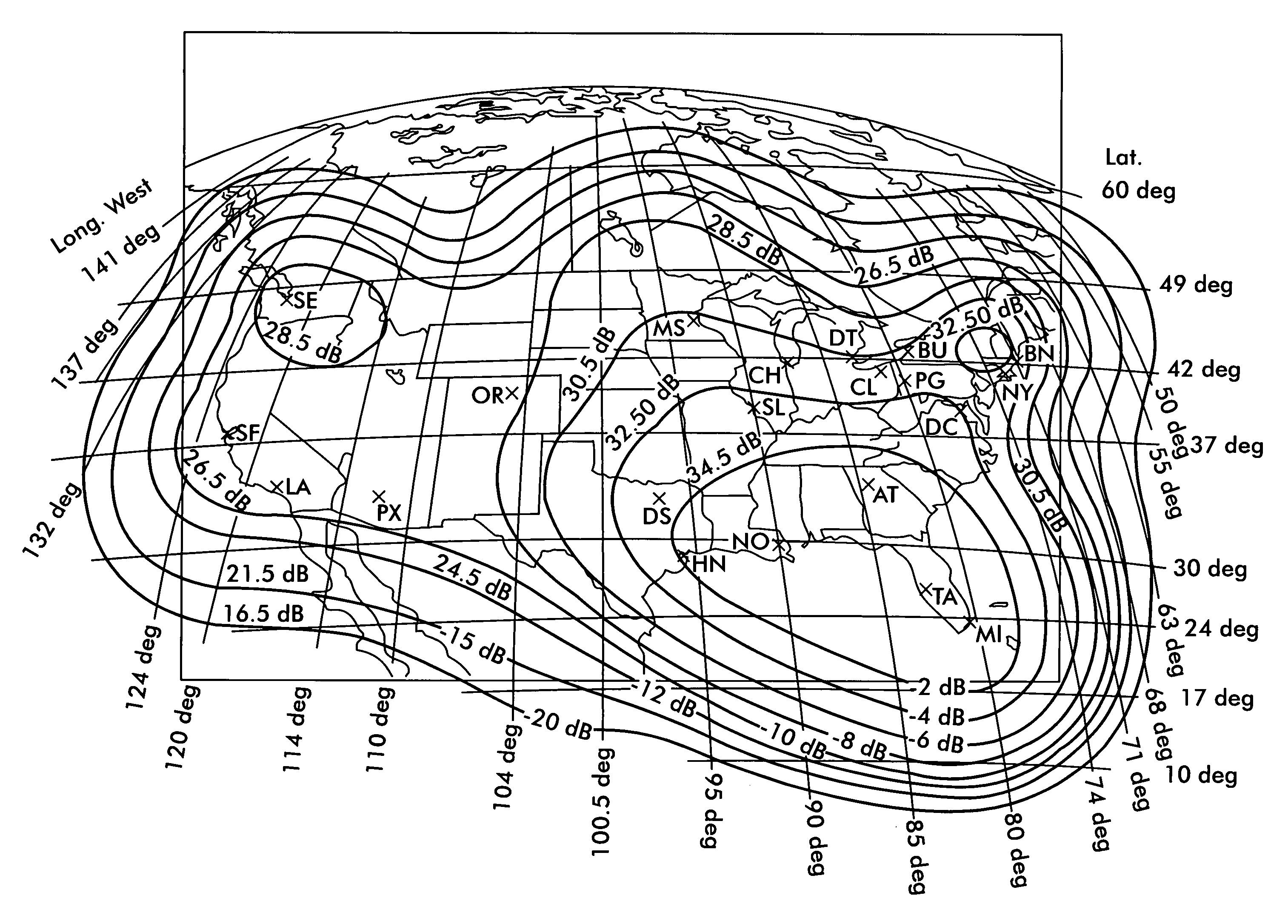
Optimum Antenna Design for the BSS in the 25 / 17 GHz Band

[0044]This example compares two designs, one uses an antenna design typical of the industry today, based on FCC and ITU applications for service and the other is the optimum case, based on the method of the present invention. The two designs assume common parameters which are listed in Table 1.

[0045]

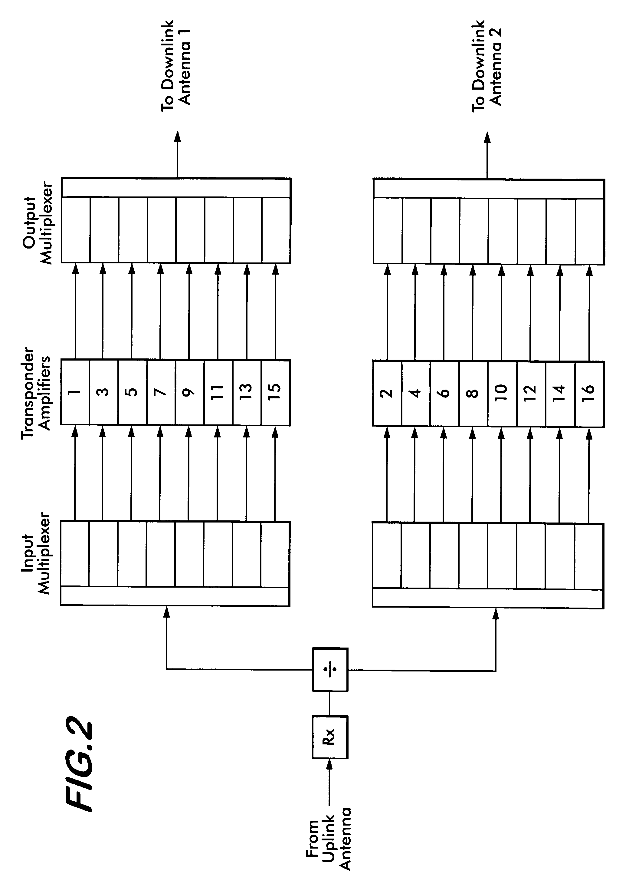
TABLE 1LIST OF ASSUMPTIONS FOR THE TWO DESIGNS.Satellite Location100.5 WRain Availability, %99.9 (99.8 for Miami)Subscriber Antenna, cm45Subscriber Earth Station Noise Temp. dBK20.4 (clear sky conditions)Uplink C / N + I, dB24.8Uplink Antenna, meters6Number of Transponders16 (in two groups of 8)Transponder Bandwidth, MHz26Uplink Frequency, GHz25Downlink Frequency, GHz17.55Uplink Transmitter Loss, dB3Downlink Transmitter Loss, dB2.5Threshold CNR, dB6.90 dB

[0046]Locations or points are either at or near major cities or at locations where the rain intensity is changing. The number of points is selected in order to characterize the antenn...

example 2

Optimum Antenna Design for the BSS in the 17 / 12 GHz Band

[0053]This example compares two designs, one is typical of the industry today, based on FCC and ITU applications for service and the optimum case, based on the method of the present invention. The two designs have common assumptions which are listed in Table 3.

[0054]

TABLE 3LIST OF ASSUMPTIONS OF THE TWO DESIGNS.Satellite Location114.5 WRain Availability, %99.9Subscriber Antenna, cm45Subscriber Earth Station Noise Temp. dBK20.4 (clear sky conditions)Uplink C / N + I, dB25.0Uplink Antenna, m6Number of Transponders16 (in two groups of 8)Transponder Bandwidth, MHz26Uplink Frequency, GHz17.55Downlink Frequency, GHz12.45Uplink Transmitter Loss, dB3Downlink Transmitter Loss, dB2.5Threshold CNR, dB6.90 dB

[0055]Locations or points are either at or near major cities or at locations where the rain intensity is changing. The number of points is selected in order to characterize the antenna performance to sufficient accuracy. Any number of po...

example 3

Comparison of Typical FSS Design in the 30 / 20 GHz Band with the Optimum Design

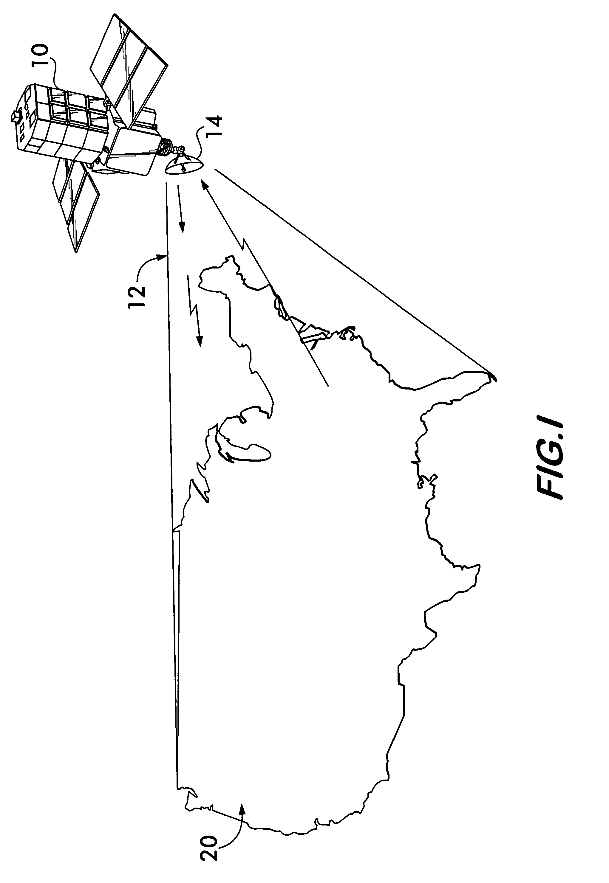
[0059]The application considered in this example is a Broadband system providing high speed two-way interconnection with the Internet. A return link from the subscriber is required and this is provided, in the example, by a small receive-transmit earth station. This example compares two uplink designs in the 30 GHz FSS band; one is typical of the industry today, based on FCC and ITU applications for service and the optimum case, based on the method of the present invention. In this case, the satellite receive antenna gain over CONUS is shaped in order to conform to the uplink rain attenuation and slant range variations, resulting in all uplink subscribers having the same subscriber antenna, power amplifier and rain availability. The two designs have common assumptions which are listed in Table 5.

[0060]

TABLE 5LIST OF ASSUMPTIONS OF THE TWO DESIGNS.Orbital Location114.5 WRain Availability Objective, %99.8Ass...


PUM


Abstract

The invention provides for the design of a single beam communication satellite system covering a single service area, either uplink, downlink or both, by which rain fade effects are totally compensated. The rain fades, characterized by fixed margins, are not exceeded for a certain percentages of time. The service area must be large enough so that the statistical rain fades (in decibels) vary significantly over the service area. The single beam antenna must be electrically large enough and must have a beam forming network capable of multiple component beams so that a gain profile can be established for the antenna which compensates for the fixed margins established over the service area. Since no subscriber has excess fixed margin this results in a minimum power system. Other significant effects such as differences in slant range and other systemic variations over the service area also can be compensated.

Description

FIELD OF THE INVENTION[0001]The present invention relates to a satellite-based communication method and system design. More particularly, the present invention relates to a satellite communication system which produces a single downlink beam from a satellite antenna having a fixed radiation pattern to provide maximum availability due to outage caused by rain to all areas covered for a given power level in an efficient, reliable and cost effective manner.BACKGROUND OF THE INVENTION[0002]In satellite communication systems, a signal is transmitted between a feeder earth station by means of an uplink to the satellite. The satellite receives the signal, amplifies it and then re-transmits the signal to a service area of the earth's surface by means of a downlink.[0003]Current satellite transmission systems include fixed gain amplifiers with their operating points determined during the design of the communication system to achieve predetermined system performance goals. The transmission sy...

Claims


Application Information

Patent Timeline
IPC IPC(8): H04W4/00
CPCH01Q1/288H01Q19/132H04B7/18523H01Q19/17Y02B60/50H04W84/06Y02D30/70
Inventor KIESLING, JOHN D.
Owner KIESLING JOHN D
Learn More