Fuel delivery system

a fuel delivery system and fuel technology, applied in the direction of machines/engines, combustion air/fuel air treatment, electric control, etc., can solve the problems of inefficient combustion, waste of fuel, unnecessary pollution, etc., and achieve the effect of maximum fuel economy and emissions performan

Inactive Publication Date: 2010-01-12
OZDEMIR PHILLIP NURI
View PDF13 Cites 9 Cited by
  • Summary
  • Abstract
  • Description
  • Claims
  • Application Information

AI Technical Summary

Benefits of technology

[0020]With regard to vaporous charge formation from liquid fuel, the present invention seeks to overcome some of the limitations and inefficiencies of the prior art. Instead of heating up reservoirs of liquid fuel to accomplish the phase transition of the fuel from liquid to vapor, I rely on a single fuel-absorbent, air-permeable evaporative wick membrane or an array of evaporative wick elements to greatly increase the evaporative surface area of the liquid fuel, and then heat the in-rushing combustion air supply which contacts such surfaces to control the transpiration from them. In such a method, the amount of heat which is supplied to the liquid fuel at the liquid-air interface is just the right amount of heat required for the vaporization, on a moment by moment basis over long-term operation of the device. In other words, by regulating the temperature and quantity of in-rushing combustion air admitted to a primary mixing region to control the heat supplied to the fuel, as it is present on the surfaces of a foraminiferous membrane or an array of transpirating elements, the amount of heat supplied for evaporation is automatically guaranteed to be the correct amount needed for such evaporation, assuming the temperature and quantity of air are correctly regulated. Furthermore, I also heat that portion of the combustion air supply which is admitted to a secondary mixing region to be mixed with the fuel rich air from the primary mixing region to dilute the eventual combustible mixture to the desired fuel strength in order that the evaporated fuel does not re-condense before reaching the combustion chamber. As a further distinction and improvement over the prior art, I am able to control the amount of in-rushing air supply which impacts the transpirating elements in the primary mixing region and the variation of the fuel / air ratio in the generated combustible mixture with a single moving control element. Having only a single moving part in the whole invention to assure its main functionality leads to a practical robustness and more economical construction than presently exists in all of the prior art.

Problems solved by technology

The incomplete mixing of the fuel and air leads to inefficient combustion, fuel wastage, and unnecessary pollution.
However, it takes a tremendous amount of heat to vaporize traditional liquid fuels for internal combustion engines.
However, in some cases, the added parasitic load inefficiency, compounded by further inefficiencies in the belt, pulley, and bearing losses from the generator, make a significant operating cost difference.
Furthermore the use of electrical resistance heating necessitates the cost and weight of expensive, heavy electrical generators and wiring harnesses; and is unsafe due to the hazard of electrical sparks and short-circuits developing in close proximity to the combustible mixtures.
The problem with using exhaust gases, however, is that it is extremely unsafe to put exhaust gases in close proximity to gasoline and combustible volatile mixtures.
The closer the exhaust gas heat source and the thinner the partition between the exhaust gas stream and the gasoline, the better the heat transfer to the gasoline and the more efficient the vaporization process; but the more dangerous the situation can be should the partition fail and some of the hot, still-burning pieces of carbon and microscopic metal fragments enter into the gasoline.
The basic problem with devices of this sub class are safety and reliability.
The interior gas tank pressures would soon go beyond practical limits unless extremely heavy pressure vessels were constructed to obviate this problem.
Furthermore, as the tank is drawn down, the changing heat transfer characteristics of the embedded radiator and the remnant fuel would represent an additional layer of complexity as far as keeping the pressure steady.
But even then, control of the varying pressures associated with the head space gases which need to be siphoned off represents a thorny engineering problem.
Another problem encountered with vapor phase fuel delivery systems is the need to control the fuel / air ratio over a wide range to allow for various engine operating conditions.
However, existing state-of-the-art capillary action evaporative wick carburetor schemes rely on ambient temperature air supplies for volatilization and have proven to be extremely difficult to control.
There is no regularity or predictability to their performance.
It is obvious that schemes which teach the use of capillary action evaporative wicks but do not teach the incorporation of an integral thermal regulating means are not practical devices.
None of these important technical issues have been addressed in the prior art.
The problem with this scheme, however, as that as the air is compressed, the air is also heated up as a natural consequence of Boyle's Law.
This extra heat of the combustion air which is admitted to the combustion chamber decreases the volumetric efficiency of the engine, remains a problem for the engine's cooling system to dissipate, and can lead to unsafe, premature detonation of the fuel / air mixture in spark ignition engines.

Method used


Image

  • Fuel delivery system
  • Fuel delivery system
  • Fuel delivery system

Examples


Embodiment Construction

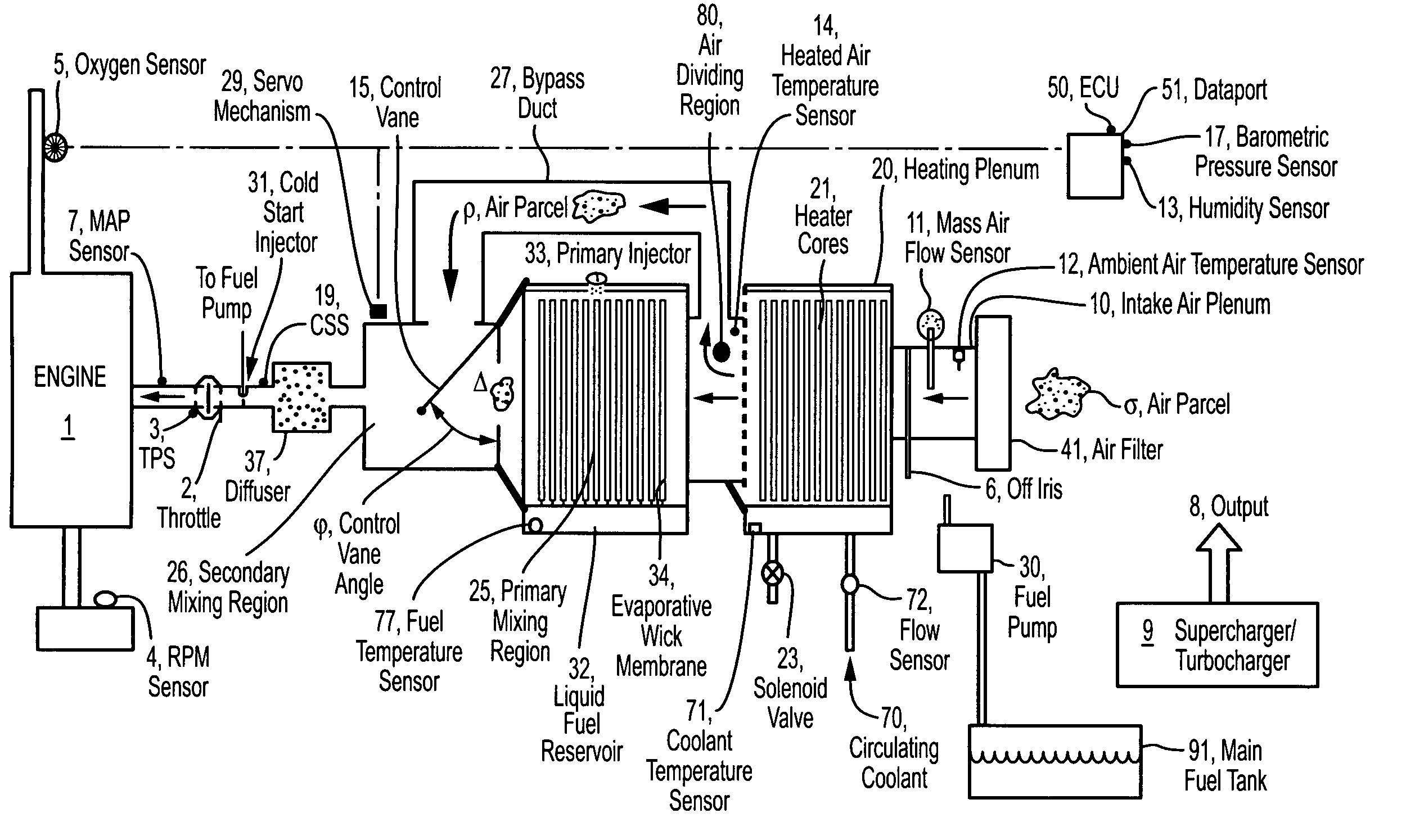
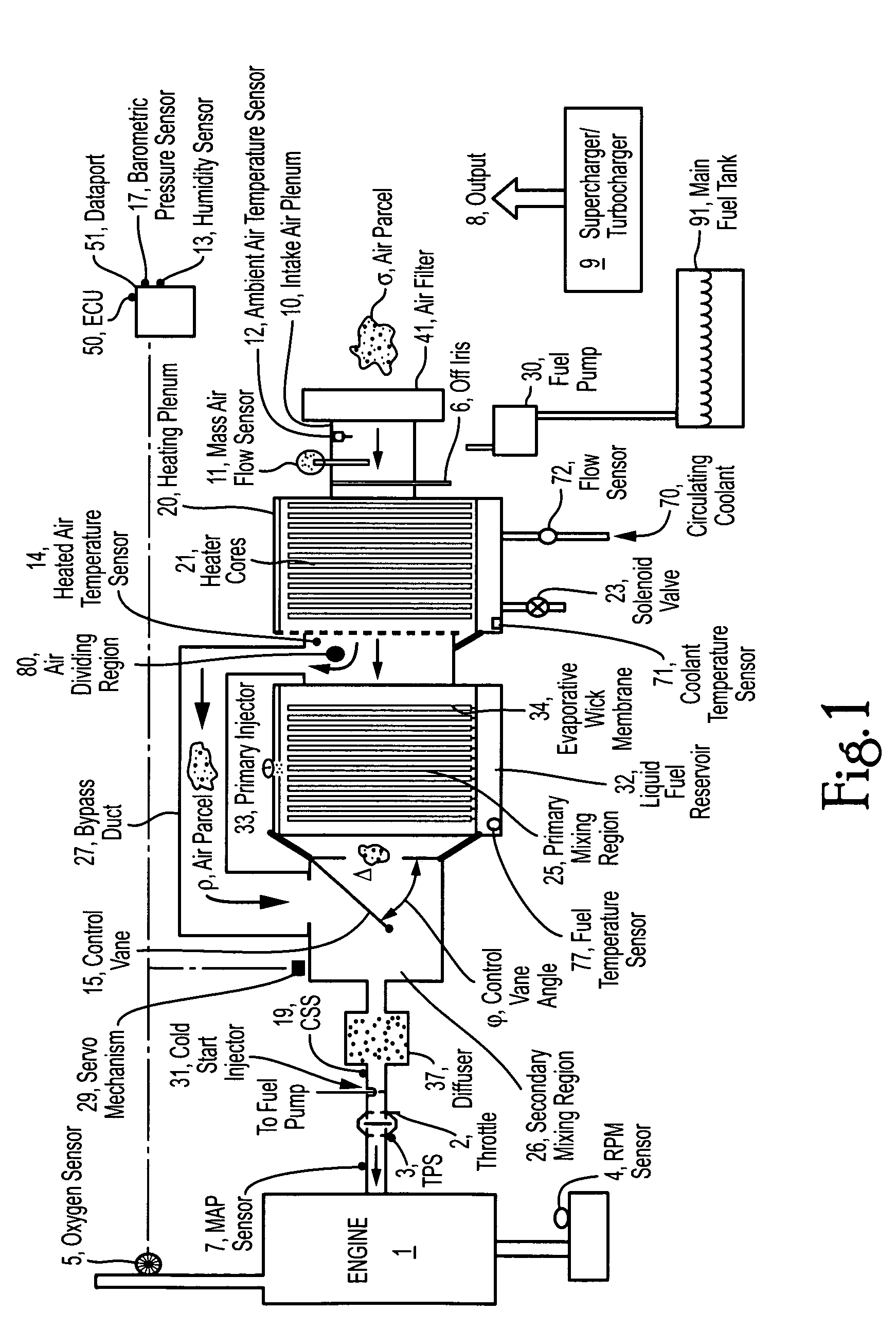
[0036]When used with a supercharger (9), the invention comprises the use of an intake air plenum (10) which receives combustion air from the output airstream (8) of a supercharger, or turbo-charger. When used without a supercharger or turbo-charger, the invention comprises the use of an intake air plenum (10) which draws fresh combustion air (air parcel sigma.) from the atmosphere into the invention for processing. In either case, intake air plenum (10) receives, transmits and defines, an airstream. Since it is desired that the total quantity of air to be combusted is measured, intake air plenum (10) also supports the emplacement of an mass air flow sensor (11). It is also desired that the temperature and humidity of the incoming combustion air be measured. Thus intake air plenum (10) also supports an ambient air temperature sensor (12) and a humidity sensor (13). These sensors communicate the results of their readings concerning the characteristics of the intake airstream (represen...


PUM


Abstract

Fuel delivery system for an internal combustion engine comprising a method and apparatus for generating and delivering a homogeneous charge with a variable fuel / air ratio which relies on fuel-absorbent, air-permeable evaporative wick membranes in a primary mixing region to which a portion of thermally-regulated air from an air dividing region has come. A single moving control element is used to control the quantity of in-rushing air in the primary mixing region, and therefore the amount of fuel rich air produced in this primary mixing region, and at the same time this single moving control element modulates both the quantity of fuel rich air and the quantity of regular fuel-free combustion air which are brought together in a secondary mixing region where they combine in the desired ratio to form a homogeneous charge with a variable fuel / air ratio. The use of a single moving control element allows extremely economical construction. A further advantage of this method is extremely rapid and accurate control of the fuel / fair ratio of the charge which is generated. The method can be used to safely and reliably generate clean-burning combustible mixtures for internal combustion engines, and to cool supercharged and turbocharged airstreams. Electronic control means are also provided to calculate the correct fuel / air ration under various engine operating and environmental conditions and so that spark plug timing and electromechanical valve timing can be adjusted in concert with adjustments to the fuel / fair ratio so that optimum fuel economy and emissions performance is obtained.

Description

CROSS-REFERENCE[0001]This application claims the benefit of earlier-filed provisional applications 60 / 677,299 (“Method of Generating a Homogeneous Charge with a Variable Fuel / Air Ratio”) filed on May 4, 2005 and 60 / 699,589 (“Method of Cooling a Supercharge”) filed on Jul. 18, 2005.BACKGROUND OF THE INVENTION[0002]1. Field of the Invention[0003]This invention relates to the problem of delivering a combustible mixture of fuel and air to an internal combustion engine or other combustion appliance. It also relates to the problem of cooling a supercharge.[0004]2. Background Art[0005]Conventional carburetors and fuel injectors for internal combustion engines, as well as for other appliances, generate a heterogenous two phase product which consists of a liquid fuel phase and a gaseous combustion air phase. The incomplete mixing of the fuel and air leads to inefficient combustion, fuel wastage, and unnecessary pollution. Estimates vary, but some say up to 40-50% of fuel is wasted because of...

Claims


Application Information

Patent Timeline
Patent Type & Authority Patents(United States)
IPC IPC(8): F02M51/00
CPCF02D41/0002F02M31/183Y02T10/128Y02T10/126Y02T10/42Y02T10/12Y02T10/40
Inventor OZDEMIR, PHILLIP NURI
Owner OZDEMIR PHILLIP NURI
Why Eureka
Try Eureka